
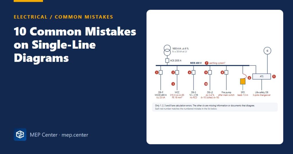
The single-line diagram is read by the utility, the switchboard builder, the contractor, the commissioning engineer and, years later, the maintenance team. When reviewers return an SLD, it is rarely for a dramatic error. It is for missing data and for two documents that disagree.
The 10 mistakes, and what to do instead
- Breaking capacity below the fault level. A 400 A MCCB with Icu 25 kA sits on a busbar with Ik ≈ 38 kA. Why it is wrong: the device may not clear the fault safely. Instead: Icu ≥ prospective Ik at that point (here a 50 kA device), or a tested cascading combination stated on the SLD.
- Device larger than the cable rating. 315 A protecting 4 × 95 mm² Cu XLPE rated about 298 A on tray. Why: In ≤ Iz is violated, so the cable can overheat. Instead: 250 A if the load allows, or 4 × 120 mm² (about 346 A).
- PE too small. PE 16 mm² with 95 mm² phase conductors. Why: the simplified rule gives S/2 = 47.5 → 50 mm² for phases above 35 mm². Instead: 50 mm², or show an adiabatic check that justifies less.
- Socket circuits without RCDs. Twelve C16 socket circuits with no 30 mA protection. Why: sockets up to 32 A for ordinary persons need additional protection. Instead: RCBOs or RCDs of the right type (see RCD types).
- 3-pole ATS with a separately earthed generator. Why: with the generator star point earthed at the set, an unswitched neutral creates parallel neutral–earth paths and confuses earth-fault protection. Instead: a 4-pole changeover.
- SPD drawn with 1.5 m leads. Why: at about 1 kV per metre this adds about 1.5 kV to Up. Instead: a + b ≤ 0.5 m; see how to connect an SPD.
- No earthing system on the main board. Why: device selection, RCD use and disconnection checks all depend on it. Instead: state TN-S / TN-C-S / TT / IT, the MET and the electrode.
- Fire pump fed after the main switch. Why: opening the main switch during a fire would stop the pump. Instead: feed it ahead of the main switch or from a dedicated life-safety supply, with a fire-resistant feeder, according to national rules.
- Sub-main with 3.4 % voltage drop. Why: it leaves too little for final circuits within the overall limit. Instead: keep sub-mains to about 1–2 %, upsize the cable, and show ΔU on every feeder (voltage drop calculator).
- SLD and cable schedule disagree. 4 × 10 mm² on the SLD, 4 × 16 mm² in the schedule. Why: the contractor will install one of them, and you do not know which. Instead: one cable reference, one set of data, generated from the same source.
What every board and feeder should show
| For each board | For each feeder |
|---|---|
| Name, voltage, frequency | Device type, In, Icu, poles |
| Earthing system | Trip settings (Ir, Isd, tsd, Ii, earth fault) |
| Prospective Ik (and ip at the main board) | RCD sensitivity and type |
| Busbar rating, form of separation, IP | Cable reference, cores × size + PE, method, length |
| Metering and SPD | Voltage drop at the end, Ik at the receiving board |
| Spare ways (≥ 20 %) | Life-safety circuits marked with fire-resistant cable type |
Typical values — verify with the edition adopted locally.
Drawing tips: draw from the source downwards, keep the main busbar horizontal, and use the same feeder order as the physical board. Draw life-safety circuits visibly separate. For the calculations behind the numbers, see cable sizing and voltage drop and MCB selection and discrimination. For load sharing between phases, see phase balancing and panel schedules.
Electrical Power Systems Design for Buildings
35 modules from the MV connection to the socket: transformers, short circuit, protection and selectivity, cable sizing, boards, generators, earthing, surge and lightning protection. Includes 50 % off TEKHAT.
Modules 1–3 are free, no account needed · full course €15,00 one-time
FAQ
What information must be on a single-line diagram?
For every board: the earthing system, prospective fault current, busbar rating and SPD. For every feeder: the device type, rating, breaking capacity and settings, RCD type, cable size and length, and voltage drop. Without this data, others downstream have to guess.
What is the most common SLD mistake?
Missing or inconsistent information rather than wrong calculations. Typical examples are no earthing system, no fault level, and cable sizes that differ between the SLD and the cable schedule.
Should the ATS be 3-pole or 4-pole?
Where the generator neutral is earthed at the set (a separately derived source), use a 4-pole changeover so that the neutral is switched. A 3-pole ATS fits only where the neutral is not separately earthed at the generator. Check the local rules.
TEKHAT – Single-Line Diagram & Load Schedule
Draw panel single-line diagrams and load schedules in minutes, with breaker, RCD and cable sizing. Buyers of the Electrical Power Systems Design course get 50 % off.
Free install from the Microsoft Store · 30-day trial · licence 20 € for all your devices or €15 per computer on our site
More Electrical articles
- UPS Sizing: kVA, kW and Battery Autonomy in Practice
- EV Charger Installation: An Electrical Checklist
- Emergency Lighting: Quick Design Rules (EN 1838 / NFPA 101)
- MCB Selection and Discrimination: A Practical Design Guide
- TN-S vs TN-C-S vs TT Earthing: Systems Explained (Plus IT)
- How to Measure Earth Electrode Resistance (Fall-of-Potential)