
Voltage drop is the first thing a reviewer checks on a load schedule, and the most common reason a cable size gets bumped up late in a project. The catch is that voltage drop is only half the story: a cable can pass the drop check and still be too small for its breaker.
This guide shows the quick method practising engineers use (mV/A/m), the limits to design to, and one worked example that sizes a sub-main and a final circuit together, so you see how the drops add up.
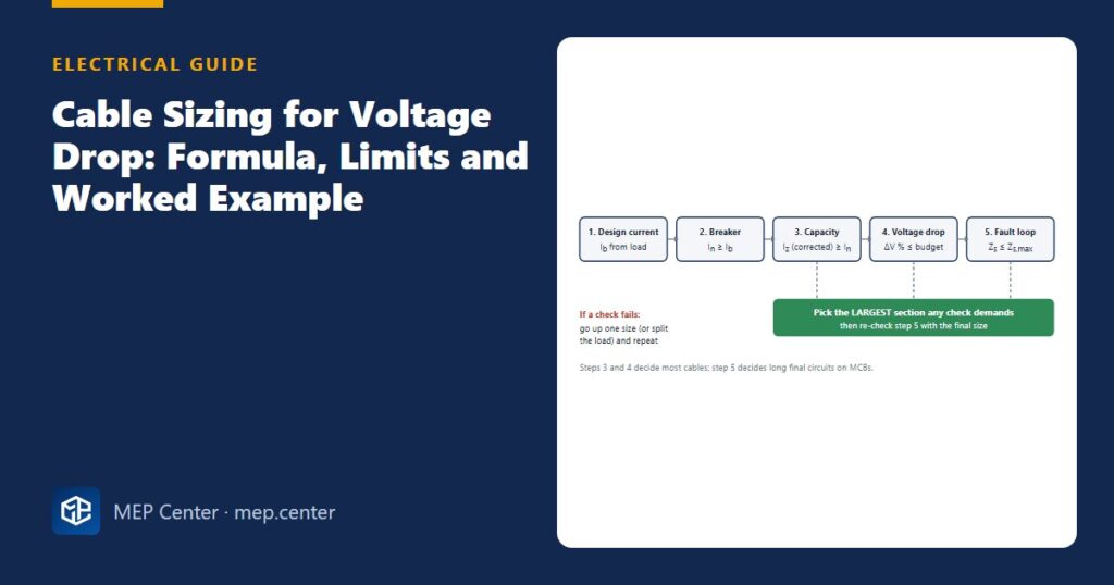
- Size every cable twice: once for current (Ib ≤ In ≤ Iz) and once for voltage drop. Keep the larger size.
- Use the quick formula ΔV = mV/A/m × Ib × L / 1000 with the cable’s mV/A/m value from manufacturer data or your code’s tables.
- Calculate with the design current Ib, not the breaker rating, and with the one-way route length.
- Typical limits from the origin of the installation: 3 % for lighting, 5 % for other loads (public LV supply).
- Drops add up: the sub-main and the final circuit share one budget, so give the sub-main 1–2 % and leave the rest for final circuits.
- Long, lightly loaded circuits are decided by voltage drop; short, heavily loaded or grouped circuits are decided by current capacity.
The two checks every cable must pass
A cable is correctly sized when it carries the load without overheating and delivers an acceptable voltage at the far end. These are separate checks, and you need both.
Check 1 — current-carrying capacity
The classic chain is:
Ib ≤ In ≤ Iz
Ib is the design current of the circuit (A), In the rated current of the protective device (A), and Iz the current-carrying capacity of the cable after correction for ambient temperature, grouping and thermal insulation (A). In practice: Iz = tabulated capacity × Ca × Cg × Ci.
The installation method matters a lot. The same 2.5 mm² copper cable is good for roughly 24 A in conduit on a wall and about 27 A clipped direct, before any correction. Bunch it with two other circuits and the grouping factor (around 0.70 for three circuits) takes it under 19 A.
Check 2 — voltage drop
Voltage drop decides how well equipment works at the end of the line: motors start badly, LED drivers flicker and heaters lose output when the voltage sags. It is a design limit rather than a safety limit, but reviewers enforce it just as strictly.
The quick voltage-drop formula (mV/A/m)
Cable tables and manufacturer data give a voltage drop per amp per metre for each cable size, already corrected to the conductor’s operating temperature and including reactance for larger sizes. With it, the calculation is one line:
ΔV = mV/A/m × Ib × L / 1000
ΔV is the voltage drop (V), mV/A/m the cable’s tabulated value (millivolts per amp per metre), Ib the design current (A) and L the one-way route length (m). Dividing by 1000 turns millivolts into volts. For percent: ΔV % = ΔV / U × 100, with U = 230 V for single-phase and 400 V for three-phase circuits.
The single-phase value already includes the return conductor, and the three-phase value is about √3/2 (0.87) of the single-phase one. So do not multiply by 2 or √3 again.
| Copper, PVC-insulated multicore (70 °C) | 1-phase mV/A/m | 3-phase mV/A/m |
|---|---|---|
| 1.5 mm² | ≈ 29 | ≈ 25 |
| 2.5 mm² | ≈ 18 | ≈ 15 |
| 4 mm² | ≈ 11 | ≈ 9.5 |
| 6 mm² | ≈ 7.3 | ≈ 6.4 |
| 10 mm² | ≈ 4.4 | ≈ 3.8 |
| 16 mm² | ≈ 2.8 | ≈ 2.4 |
| 25 mm² | ≈ 1.75 | ≈ 1.5 |
No table at hand? Use resistivity at operating temperature: ΔV = 2 × ρ × L × Ib / S for single-phase and √3 × ρ × L × Ib / S for three-phase, with S the cross-section (mm²) and ρ ≈ 0.0225 Ω·mm²/m for copper or ≈ 0.036 Ω·mm²/m for aluminium. The 20 °C value (0.0179 for copper) that many spreadsheets use underestimates the drop by about 20 %. Aluminium needs roughly 1.6 times the copper cross-section for the same drop.
All limits, mV/A/m values, capacities and correction factors in this article are typical — verify with the edition adopted locally and with manufacturer data for the actual cable.
What limit to design to
IEC 60364 practice (and BS 7671) recommends limits measured from the origin of the installation — the supply terminals — to the equipment, not from each board:
- Lighting: 3 % when supplied from the public LV network.
- Other uses (sockets, heating, motors): 5 % from the public LV network.
- Own transformer (private MV/LV substation): typically 6 % lighting and 8 % other, because the supply side is under your control.
Because the limit is cumulative, split it into a budget: for example 1–1.5 % for the main feeder and sub-mains, the rest for final circuits. Set the targets per circuit category, not one number for the whole project. A blanket 1.5 % target on every short socket circuit forces 4 mm² where 2.5 mm² is perfectly adequate.
Motor starting is a separate case: a direct-on-line start draws 6–8 times the running current, and the momentary dip at the motor terminals is often limited to 10–15 %. Check large motors on long feeders with their starting current.
Worked example: sub-main plus final circuit
Inputs
- Sub-main: 400 V three-phase, 30 kW sub-board, power factor 0.85, route length 65 m, multicore copper PVC cable clipped to a wall (method C), bunched with two other circuits.
- Final circuit: 230 V single-phase radial, 2000 W heater outlet (pf ≈ 1), 60 m from the sub-board, two-core copper PVC cable.
- Limit: 5 % total from the origin (other uses, public supply). The main board is at the origin.
Step 1 — sub-main design current
Ib = P / (√3 × U × cos φ) = 30 000 / (1.732 × 400 × 0.85) = 30 000 / 588.9 = 50.9 A. Choose a 63 A breaker (In = 63 A ≥ 50.9 A).
Step 2 — sub-main current capacity
Grouping factor for three bunched circuits ≈ 0.70.
16 mm²: 76 A × 0.70 = 53.2 A < 63 A → fails.
25 mm²: 96 A × 0.70 = 67.2 A ≥ 63 A → passes.
Step 3 — sub-main voltage drop (25 mm², 1.5 mV/A/m)
ΔV = 1.5 × 50.9 × 65 / 1000 = 4.96 V → 4.96 / 400 = 1.24 %.
(16 mm² would give 2.4 × 50.9 × 65 / 1000 = 7.94 V = 1.99 %: acceptable for drop, so current capacity decided this cable.)
Step 4 — final circuit current
Ib = 2000 / 230 = 8.7 A → 16 A breaker; 2.5 mm² is ample for current.
Step 5 — final circuit voltage drop
Budget left: 5 − 1.24 = 3.76 %.
2.5 mm² (18 mV/A/m): ΔV = 18 × 8.7 × 60 / 1000 = 9.39 V → 4.08 % > 3.76 % → fails (total 5.32 %).
4 mm² (11 mV/A/m): ΔV = 11 × 8.7 × 60 / 1000 = 5.74 V → 2.50 % → passes.
Result
Sub-main 4 × 25 mm² on 63 A; final circuit 2 × 4 mm² + protective conductor on 16 A. Total drop 1.24 + 2.50 = 3.74 % ≤ 5 %.
Sanity check
Rule of thumb: 2.5 mm² single-phase drops about 1 % per 128 A·m (2.3 V ÷ 0.018 V/A·m). Our 8.7 A × 60 m = 522 A·m ≈ 4.1 % — matches step 5. Had the outlet been 25 m away, 2.5 mm² would give 18 × 8.7 × 25 / 1000 = 3.91 V = 1.70 %, comfortably inside the budget.
Length is what usually forces the upsize
Voltage drop grows linearly with length, so for each cable size there is a maximum length at a given current. Plotting it makes the decision obvious and is a nice check to keep next to your schedule.
Quick reading: below about 55 m the smaller cable is fine; beyond it, go up a size or move the sub-board closer to the load. On large projects, moving a sub-board 20 m often saves more copper than any amount of upsizing.
Do not forget the fault loop
A long final circuit protected by an MCB has one more hurdle: during an earth fault the loop impedance must be low enough for the breaker’s magnetic trip to operate within the required disconnection time. Upsizing for voltage drop usually helps here too, but check it. The method and typical maximum Zs values are covered in our guide to MCB selection and discrimination, and the supply-side impedance depends on your earthing system (TN or TT).
Doing it for a whole project
On a real building you repeat these checks for hundreds of circuits, and every change in the load list means recalculating. Keep three habits: calculate from the circuit list rather than by hand per circuit, carry the upstream drop down to each board automatically, and re-run the check after phase balancing, because moving a load between boards changes the sub-main current.
Our TEKHAT program does exactly this: it reads the circuit list, checks voltage drop and current capacity for every circuit against per-category targets, flags undersized circuits with a suggested size, and writes the corrected schedule and the single-line diagram (DXF) in one run.
Common mistakes
- Using the breaker rating instead of the design current for voltage drop — it overstates the drop and wastes copper.
- Applying the limit per board instead of from the origin, so sub-main and final circuit together exceed 5 %.
- Using 20 °C resistivity (0.0179 Ω·mm²/m) — the cable runs hot and the real drop is about 25 % higher.
- Multiplying a tabulated mV/A/m value by 2 or √3 again; the table already includes it.
- Measuring length on plan only and forgetting risers, drops to equipment and detours around shafts.
- Checking voltage drop but not grouping factors, so a bunched cable passes on paper and runs hot in the tray.
- Forgetting the motor starting dip on long feeders to pumps and fans.
Quick checklist
- Ib calculated from the real load (with power factor for three-phase).
- In ≥ Ib and corrected Iz ≥ In, with ambient, grouping and insulation factors listed.
- Route length includes vertical runs and a sensible allowance for detours.
- ΔV % per circuit plus upstream drop ≤ category limit from the origin.
- Fault-loop impedance checked for long MCB-protected circuits.
- Cable size on the schedule, the single-line diagram and the plan all match.
Electrical Power Systems Design for Buildings
35 modules from the MV connection to the socket: transformers, short circuit, protection and selectivity, cable sizing, boards, generators, earthing, surge and lightning protection. Includes 50 % off TEKHAT.
Modules 1–3 are free, no account needed · full course €15,00 one-time
FAQ
What is the maximum allowed voltage drop for a building installation?
Typical IEC and BS 7671 practice is 3 % for lighting and 5 % for other loads, measured from the origin of the installation when supplied from the public LV network. With your own transformer, 6 % and 8 % are common. Always confirm the edition adopted locally and any stricter project specification.
Should I use the breaker rating or the load current for voltage drop?
Use the design current of the circuit (Ib). The breaker rating is used for the current-capacity check, not for voltage drop. Using the breaker rating overstates the drop and leads to oversized cables.
How do I calculate voltage drop with mV/A/m values?
Multiply the cable’s mV/A/m value by the design current in amps and the one-way length in metres, then divide by 1000 to get volts. Divide by 230 V or 400 V and multiply by 100 for percent. The single-phase and three-phase tabulated values already include the return path, so do not multiply by 2 or √3.
Does voltage drop or current capacity decide the cable size?
Whichever demands the larger cross-section. Long, lightly loaded circuits are usually decided by voltage drop, while short circuits, grouped cables and hot locations are decided by current-carrying capacity.
Can I use aluminium cable to save cost?
Yes, for larger feeders aluminium is common, but it needs roughly 1.6 times the copper cross-section for the same voltage drop and suitable terminations. It is rarely used below 16 mm².
TEKHAT – Single-Line Diagram & Load Schedule
Draw panel single-line diagrams and load schedules in minutes, with breaker, RCD and cable sizing. Buyers of the Electrical Power Systems Design course get 50 % off.
Free install from the Microsoft Store · 30-day trial · licence 20 € for all your devices or €15 per computer on our site
More Electrical articles
- Cable Gland Selection: Size, Armour, IP and Earthing
- 10 Common Mistakes on Single-Line Diagrams
- Emergency Lighting: Quick Design Rules (EN 1838 / NFPA 101)
- How to Measure Earth Electrode Resistance (Fall-of-Potential)
- Busbar Trunking vs Cables: Selection in Practice
- How to Connect an SPD in a Distribution Board (the 0.5 m Rule)