
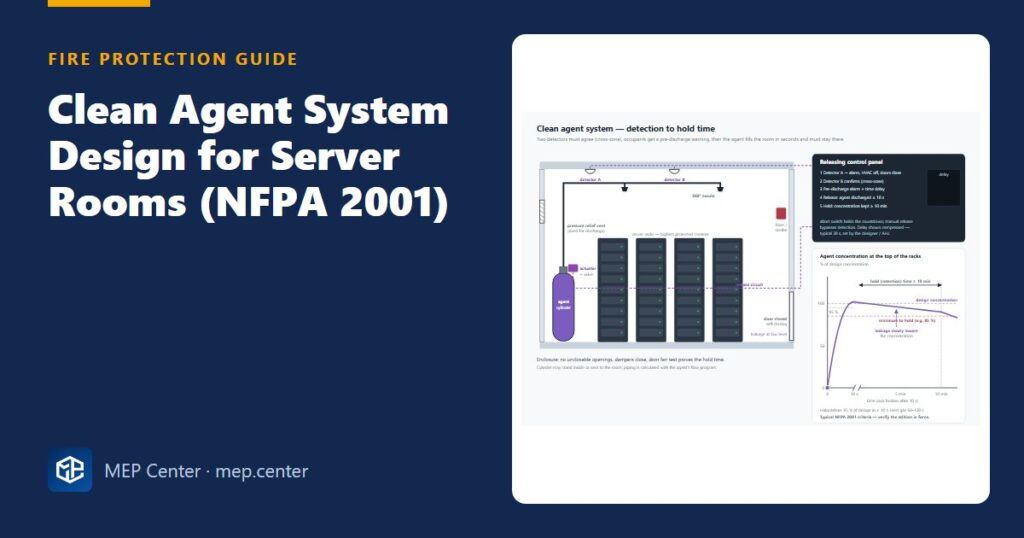
Water and server racks do not mix, which is why server rooms are usually protected by a clean agent system that floods the room with gas and leaves no residue. Clean agent design is not “sprinklers with gas”, though. You design for a concentration instead of a density, the room itself becomes part of the system, and people’s safety sets hard limits. This guide shows you how to design a clean agent system to NFPA 2001, with a full server-room example for three common agents.
- Design for concentration: agent quantity follows from the net volume, the design concentration and the minimum room temperature.
- Design concentration = extinguishing concentration × safety factor: 1.2 for Class A, 1.3 for Class B, and 1.35 for Class C (2012 edition onwards).
- Calculate the quantity at the minimum temperature, then check the concentration at the maximum temperature against the NOAEL.
- Include the raised floor and ceiling void if they communicate with the room. Never deduct racks or furniture.
- Halocarbons must reach 95 % of the design concentration in 10 s. Inert gases must do so in 60 s (120 s for Class A/C where the edition allows). Hold for at least 10 min.
- Prove the room with a door fan test and provide pressure relief, which is essential for inert gases.
What a clean agent system is (and is not)
A clean agent is a non-conductive gaseous extinguishant that leaves no residue. NFPA 2001 covers two families: halocarbons, stored as liquids under nitrogen pressure, which extinguish mainly by absorbing heat, and inert gases, stored at 150–300 bar, which lower the oxygen level. CO2 is not a clean agent; it has its own standard and very different safety rules.
Almost all systems are total flooding: the agent fills the enclosure to a uniform concentration and must stay there long enough for the fire to go out. In a typical server room the clean agent protects the room, the raised floor and the ceiling void. A preaction sprinkler system often provides the building-code sprinkler protection alongside it. The two are complementary unless the authority explicitly accepts the agent as the only system.
Concentrations, constants and limits in this guide are typical NFPA 2001 values in our own summary. Verify them with the edition adopted locally and with the listing and design manual of the system you use; the listing always governs.
Choosing the agent
| Agent (generic) | Typical design concentration, Class A → C | NOAEL / LOAEL | Practical notes |
|---|---|---|---|
| HFC-227ea | ≈ 6.25–7.0 % | 9.0 % / 10.5 % | The most widely installed halocarbon; high global warming potential, subject to phase-down rules |
| FK-5-1-12 (fluoroketone) | ≈ 4.2–4.7 % | 10 % / > 10 % | Very low GWP; liquid at room temperature; large safety margin |
| HFC-125 | ≈ 8–9 % | 7.5 % / 10 % | Design is often near or above the NOAEL, so check occupancy carefully |
| IG-541 (N₂/Ar/CO₂) | ≈ 34–42 % | 43 % / 52 % | Cylinder bank and room needed; strong pressure relief |
| IG-55, IG-01, IG-100 | ≈ 36–45 % | 43 % / 52 % | As IG-541; the limits are oxygen-based |
The choice is usually driven by space, vent location, cost and environmental policy: halocarbons need one or two cylinders, inert gases a cylinder room and a large vent.
Design concentration and safety
Three concentrations matter, and mixing them up is the most common error:
- Minimum extinguishing concentration (MEC): found by fire test for a given fuel.
- Minimum design concentration: MEC × safety factor. The factors are 1.2 (Class A), 1.3 (Class B) and 1.35 (Class C, energised equipment up to about 480 V), the Class C factor being applied to the Class A value.
- Design concentration: what you design for, never less than the minimum.
For people, the critical effect of halocarbons is cardiac sensitisation; for inert gases it is low oxygen. Halocarbons may be designed up to the NOAEL in normally occupied rooms. Inert gases up to about 43 % (≈ 12 % O₂) allow a 5-minute exposure. Between 43 % and 52 % the exposure drops to about 3 minutes. Above 52 % the space must be normally unoccupied. If a Class B fuel is present, such as a generator day tank, the room is no longer “Class A/C”, so take the highest concentration of any fuel present.
How much agent: the two equations
Halocarbons: W = (V / S) × C / (100 − C)
- W is the agent mass in kg, V the net volume in m³ and C the design concentration in %.
- S is the specific vapour volume in m³/kg at the minimum room temperature T (°C), with S = k₁ + k₂·T. For HFC-227ea, S = 0.1269 + 0.000513·T. For FK-5-1-12, S = 0.0664 + 0.000274·T.
The term C/(100 − C) allows for the agent–air mixture pushed out of the room during discharge. To check the concentration at another temperature, use C = 100 × (W·S/V) / (1 + W·S/V) with S at that temperature.
Inert gases: X = (Vs / S) × ln[100 / (100 − C)]
- X is m³ of agent per m³ of room, referred to 21 °C.
- Vs is the specific volume at 21 °C, and S the value at the minimum temperature. For IG-541, S = 0.65799 + 0.00239·T.
The logarithm models continuous mixing and outflow. At 40 %, X is about 0.51 m³/m³, not 0.40.
Net volume: add every space that communicates with the protected room. Deduct only permanent, impermeable building elements such as columns. Never deduct racks, cabinets or furniture, because agent fills them and they can be moved. At altitude, multiply the quantity by the standard’s correction factor, roughly 0.88 at 1000 m (3300 ft).
Worked example: 8 × 6 m server room
Inputs. Server room 8.0 × 6.0 m with a clear height of 3.0 m. Raised floor void 0.6 m and ceiling void 0.8 m, both communicating with the room and both protected. Hazard: Class A (cables, plastics) and Class C (energised IT below 480 V), no Class B fuel. Minimum temperature 20 °C, maximum (HVAC failure) 30 °C. Sea level. Normally occupied for short periods.
- Net volume. Room 8.0 × 6.0 × 3.0 = 144.0 m³. Raised floor 8.0 × 6.0 × 0.6 = 28.8 m³. Ceiling void 8.0 × 6.0 × 0.8 = 38.4 m³. Total 211.2 m³, with no deductions because the racks are permeable.
- Design concentration (assumed listings). HFC-227ea: MEC 5.2 % × 1.35 ≈ 7.0 % (Class C governs; Class A would be 6.25 %). FK-5-1-12: MEC 3.5 % × 1.35 ≈ 4.7 % (Class A: 4.2 %).
- HFC-227ea quantity. S20 = 0.1269 + 0.000513 × 20 = 0.1372 m³/kg. C/(100 − C) = 7/93 = 0.07527. W = 211.2 / 0.1372 × 0.07527 = 115.9 kg, split as room 79.0, raised floor 15.8 and ceiling void 21.1 kg.
- Check at 30 °C. S30 = 0.1423. W·S/V = 115.9 × 0.1423 / 211.2 = 0.0781. C = 100 × 0.0781 / 1.0781 = 7.24 %, which is below the 9.0 % NOAEL ✓, so the room may stay normally occupied.
- FK-5-1-12 quantity. S20 = 0.0664 + 0.000274 × 20 = 0.07188. C/(100 − C) = 4.7/95.3 = 0.04932. W = 211.2 / 0.07188 × 0.04932 = 144.9 kg. At 30 °C: 4.87 %, far below the 10 % NOAEL ✓.
- Cylinders (assumed fill data). HFC-227ea at about 1.15 kg/L: 115.9 / 1.15 = 101 L, so one 120 L cylinder, or two 80 L at 58.0 kg each. FK-5-1-12 at 1.2–1.4 kg/L needs 104–121 L, so one 120 L cylinder only if the listed fill is at least 1.21 kg/L; otherwise two 80 L at 72.5 kg each.
- Nozzles. One 360° nozzle at the centre of the room ceiling (8 × 6 m and 3.0 m high fit a typical single-nozzle, single-tier listing), one in the raised floor and one in the ceiling void. The manufacturer’s flow calculation must confirm a discharge time of ≤ 10 s.
- Inert alternative (IG-541 at 40 %). Vs = 0.65799 + 0.00239 × 21 = 0.70818. S20 = 0.70579. X = (0.70818 / 0.70579) × ln(100/60) = 0.513 m³/m³. Agent = 0.513 × 211.2 = 108.3 m³ (≈ 153 kg). That is 7 cylinders of 80 L at 200 bar (≈ 15.5 m³ each) or 5 at 300 bar (≈ 22 m³ each), depending on manufacturer data.
- Relief vent for IG-541. 60 s discharge: average 108.3 / 60 = 1.80 m³/s, peak ≈ 1.1 × 1.80 = 1.99 m³/s. Allowable room pressure 250 Pa (from the architect), mixture density 1.25 kg/m³, Cd = 0.61. √(2 × 250 / 1.25) = 20 m/s → A = 1.99 / (0.61 × 20) = 0.16 m² of free vent area, for example 400 × 400 mm.
Sanity check. 115.9 kg × 0.1372 m³/kg = 15.9 m³ of HFC-227ea vapour in 211.2 m³, which is 7.5 % by the simple ratio. That is slightly more than 7.0 %, as expected from the free-efflux term ✓. The FK-5-1-12 mass is higher, but its concentration is lower, and it is a dense liquid, so the cylinder volume grows less than the mass. At 1000 m altitude the HFC-227ea quantity would drop to 115.9 × 0.88 ≈ 102 kg.
Discharge time and hold time
Discharge time is a requirement, not a hope. A halocarbon must reach 95 % of the minimum design concentration within 10 seconds. A fast discharge limits fire growth and decomposition products such as hydrogen fluoride. An inert gas must do so within 60 seconds, or up to 120 seconds for Class A and C hazards where the adopted edition allows it. The manufacturer’s listed flow calculation proves this. Your job is to check that its volumes, temperatures and pipe routes match the drawings.
The concentration must then be held for at least 10 minutes, or long enough for the fire service to respond if that is longer. During this time, the concentration at the height of the highest combustible must stay above a stated fraction of the design value, 85 % of the adjusted minimum design concentration in recent editions.
Enclosure integrity: the door fan test
The calculation assumes the room holds the agent, and only a test can prove it. In a door fan test, a calibrated fan in the doorway pressurises and depressurises the room, typically in the 10–50 Pa range, and measures the leakage area. Software then predicts how fast the heavier agent–air mixture drains out through low leaks while air enters through high ones. The predicted retention time must reach the required hold time.
- Specify sealing early: fire-stopped cable and pipe penetrations, clipped or sealed ceiling tiles, sealed raised-floor edges, door seals and closers.
- Interlock the HVAC so that dampers close and external units stop on alarm, and test before handover, then annually.
Room pressure and relief venting
Adding tens of cubic metres of gas in seconds changes the room pressure. Inert gases push it strongly positive. Halocarbons first pull it negative as the liquid flashes and cools the air, then push it positive, so a two-way vent may be needed. The vent area follows the orifice relation A = Q / [Cd × √(2·ΔP / ρ)]. Get the allowable pressure in writing from the architect or structural engineer; lightweight partitions are often taken at around 250–500 Pa. Discharge the vent outside or into a large adjacent space, never into an escape stair, and use a fire-rated vent in a fire-rated wall.
Detection and release sequence
Provide a manual release at each exit, an abort switch with an agreed and posted behaviour, a maintenance lock-out, and “agent discharged” indication outside the room. The releasing panel connects to the building fire alarm; our guides to fire alarm system types and smoke and heat detector spacing cover that side.
Common mistakes
- Taking the design concentration from an old brochure or project instead of the current listing, or using the Class A factor where Class C now governs.
- Ignoring a Class B fuel, such as a generator day tank or solvent store, inside the protected volume.
- Leaving the raised floor or ceiling void unprotected or unsealed, so that the agent drains away.
- Deducting racks or furniture from the net volume.
- Not checking the maximum concentration at the highest room temperature against the NOAEL.
- No written allowable room pressure, or a relief vent discharging into an escape route.
- HVAC dampers not interlocked, so that fresh air keeps running after discharge.
- Leaving the door fan test to the last week of commissioning.
Quick checklist
- Fire classes (A, B, C) identified and the highest design concentration selected from the listing.
- NFPA 2001 edition and authority requirements recorded in the design basis.
- Net volume of every communicating space calculated, with deductions justified.
- Quantity at minimum temperature; concentration checked at maximum temperature against NOAEL/LOAEL.
- Altitude correction applied where relevant.
- Discharge and hold times stated; manufacturer’s flow calculation reviewed against the drawings.
- Sealing specified and door fan test scheduled.
- Allowable pressure obtained; vent size, location and fire rating coordinated.
- Detection zones, release sequence, abort, manual release, lock-out and signage shown.
- Cylinder location, temperature range, floor loading and access for weighing coordinated.
Fire Protection & Suppression Systems Design (NFPA)
20 narrated modules with animated diagrams, two complete worked projects (DWG + DXF), the Fire Calc Workbook and an online calculator.
Modules 1–3 are free, no account needed · full course €15,00 one-time
FAQ
How do I calculate the amount of clean agent for a room?
For halocarbons, use W = (V / S) × C / (100 − C), with the net volume V, the specific vapour volume S at the minimum room temperature and the design concentration C. Inert gases use a logarithmic equation that gives the agent volume per cubic metre of room.
Is a clean agent safe for people in the room?
Halocarbons designed at or below their NOAEL are permitted in normally occupied spaces, and inert gases up to about 43 % allow a limited exposure of about 5 minutes. A pre-discharge alarm and time delay are still required, and nobody should stay in the room during a fire.
Do I need to protect the raised floor and ceiling void?
If they communicate with the room, they are part of the protected volume. Either include them with their own nozzles and seal them, or separate them physically from the room.
What is the discharge time for a clean agent system?
Halocarbons must reach 95 % of the minimum design concentration in 10 seconds or less. Inert gases must do so within 60 seconds, or 120 seconds for Class A and C hazards where the adopted edition allows it.
Why does an inert gas system need a pressure relief vent?
Adding about half the room volume of gas in a minute pushes the room pressure far above what lightweight walls can take. A relief vent, about 0.16 m² in our 211 m³ example, releases the excess at a safe pressure.
More Fire Protection (Sprinklers, NFPA) articles
- Sprinkler Hazard Classification: LH, OH1, OH2, EH1 and EH2 Explained
- Sprinkler Hydraulic Calculation: A Step-by-Step Worked Example
- 12 Common Sprinkler Design Mistakes Reviewers Reject
- Fire Hose Cabinets and Hose Valves: EN 671 vs NFPA 14
- EN 12845 vs NFPA 13: Key Differences for Designers
- Sprinkler Spacing Rules: Areas, Wall Distances and Obstructions