
Calculation software will size your sprinkler pipes in seconds, but a reviewer will still ask whether you can defend the numbers. A sprinkler hydraulic calculation follows the water backwards, from the most remote sprinkler to the water supply, and ends with one demand point that must sit safely below the supply curve. This guide walks you through the method with a real six-sprinkler example that you can check by hand.
- Start at the most remote sprinkler with q = density × protection area, and never below the minimum pressure of 0.5 bar (7 psi) or the listed minimum.
- Every other sprinkler flows q = K√p at whatever pressure the calculation gives it, never at the minimum flow.
- Calculate friction with Hazen–Williams, using the actual internal diameter and the right C-factor (120 for wet steel, 100 for dry and preaction steel).
- A branch line identical to one you have already calculated can be added in one step with its K-equivalent: Q = Keq × √p.
- Add the outside hose allowance at the supply connection, then keep a stated margin below the supply curve (common practice: 0.7 bar / 10 psi or 10 %).
What a hydraulic calculation has to prove
A sprinkler system is not designed to discharge everywhere at once. It assumes that a fire in the most demanding part of the building opens a limited number of sprinklers. The calculation proves two things: that every sprinkler in that design area (remote area) gets at least its required flow through the real pipe network, and that the water supply can deliver the resulting flow and pressure with a margin.
The inputs come from the design basis, which in turn comes from the hazard class. If you have not fixed the class yet, start with our guide to sprinkler hazard classification. You need four numbers:
- Density: for example 8.1 mm/min (0.20 gpm/ft²) for Ordinary Hazard Group 2.
- Design area: for example 139 m² (1500 ft²) for light and ordinary hazard.
- Hose stream allowance: 950 L/min (250 gpm) for ordinary hazard.
- Duration: 60–90 min for ordinary hazard, depending on whether the alarms are monitored off-site.
The code values in this guide are NFPA 13 (2022) values in our own summary. They are typical, so verify them with the edition adopted locally and with the listing of the sprinkler you use.
The three equations you will use
Sprinkler discharge: q = K√p
Each sprinkler behaves like an orifice: q = K × √p, so p = (q / K)².
- q is the flow in L/min (gpm).
- p is the pressure at the sprinkler in bar (psi).
- K is the K-factor in L/min/bar½ (gpm/psi½). KSI = 14.4 × KUS, so the standard K5.6 sprinkler is nominally K80.
The minimum operating pressure for standard-spray sprinklers is 0.5 bar (7 psi). At that pressure a K80 (K5.6) sprinkler gives about 56 L/min (14.8 gpm). Often the density sets a higher starting pressure, so treat the 0.5 bar figure as a floor, not a target. Never mix units: K80 used with kPa gives nonsense.
Pipe friction: Hazen–Williams
Sprinkler standards use the Hazen–Williams formula for water:
SI: pf = 6.05 × 10⁵ × Q1.85 / (C1.85 × d4.87) in bar per metre, with Q in L/min and d in mm.
US: pf = 4.52 × Q1.85 / (C1.85 × d4.87) in psi per foot, with Q in gpm and d in inches.
Here d is the actual internal diameter, not the nominal size, and C is the roughness coefficient for aged pipe. Two rules of thumb are worth remembering. Going up one pipe size cuts friction by roughly 3–4 times. Doubling the flow multiplies friction by about 3.6.
Elevation
Water weighs 0.098 bar per metre of height (0.433 psi/ft). When you move backwards towards a supply that is below the sprinklers, add the elevation. When the supply is above them (a roof tank), subtract it.
Inputs that decide the answer
Shape of the remote area
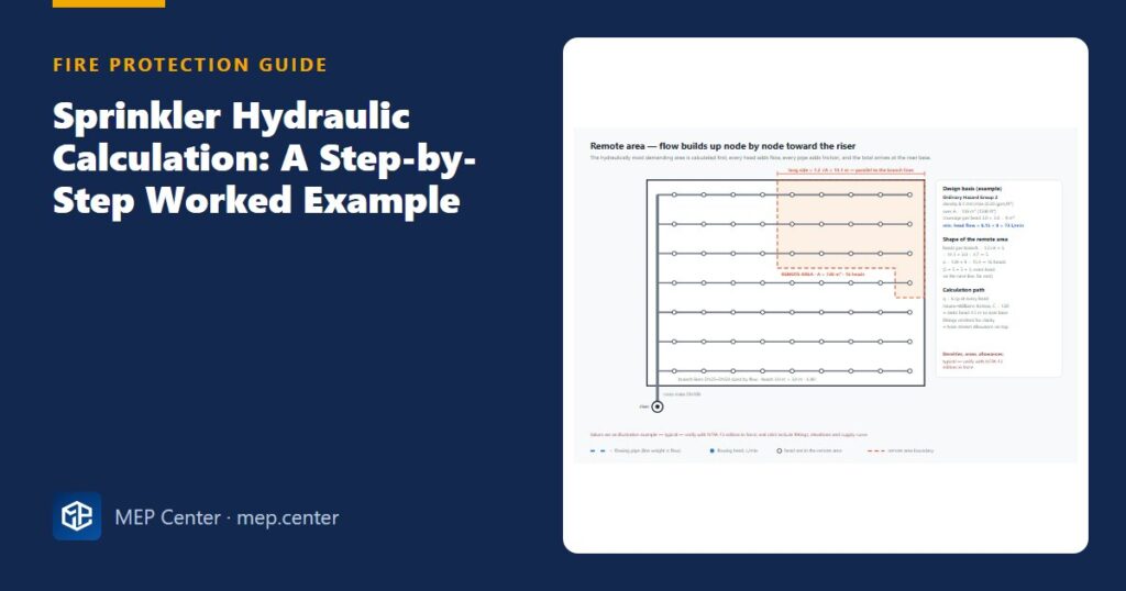
The number of flowing sprinklers is N = A / As, always rounded up. Here As is the actual protection area per sprinkler (spacing along the line × distance between lines). The area must be a rectangle at least L = 1.2√A long, measured parallel to the branch lines. For 139 m² (1500 ft²), that is 14.2 m (46.5 ft). With sprinklers 3.96 m (13 ft) apart along the line, you need 4 sprinklers per line, so a 12-head OH2 area becomes 3 lines × 4 heads. The stretched shape loads the small branch pipes, which are the weakest part of the network. Our guide to sprinkler spacing rules explains how As is measured.
C-factors and fittings
| Pipe / system | Typical C |
|---|---|
| Black or galvanised steel, wet systems (including deluge) | 120 |
| Black or galvanised steel, dry pipe and preaction | 100 |
| Copper, stainless steel, listed plastic (CPVC) | 150 |
| Cement-lined ductile iron (underground) | 140 |
Fittings are converted into an equivalent length of straight pipe. As a quick check for schedule 40 steel at C = 120, a 90° standard elbow is about 28 d, a tee with the flow turned 90° is about 60 d, a gate valve about 5 d and a swing check about 60 d. That gives 8 ft for a 1½” tee and 7 ft for a 3″ elbow. For the submitted calculation, use the equivalent-length table of the adopted edition, and take alarm valves, backflow preventers and grooved fittings from manufacturer data. Count a tee only where the flow turns. Do not count the fitting that feeds a sprinkler directly.
The node-by-node procedure
- Draw a node diagram. Number every sprinkler and every point where flows join or pipe sizes change. For each segment, note the size, actual ID, length, fittings and node elevations.
- Most remote sprinkler. q₁ = density × As, and p₁ = (q₁/K)², but not less than the minimum pressure.
- Next segment. Pressure at the next node = previous pressure + friction ± elevation.
- Next sprinkler. q = K√p at that new pressure. Add it to the running total.
- End of the branch line. Work out Keq = Q / √p at the cross main. An identical line further along then flows Q = Keq × √pnew.
- Cross main, riser, feed main. Add friction, elevation and device losses up to the supply point.
- Hose and supply. Add hose flow where it is drawn off and compare the demand with the supply curve.
Worked example: six sprinklers in an OH2 workshop room
Inputs. A rated workshop room designed by the room design method, Ordinary Hazard Group 2: 0.20 gpm/ft² (8.1 mm/min). The room is 11.9 × 6.1 m (39 × 20 ft) = 72.5 m² (780 ft²). It has 6 upright K80 (K5.6) sprinklers, 3 on each of 2 branch lines, spaced 3.96 m (13 ft) along the lines and 3.05 m (10 ft) between them, so As = 12.08 m² (130 ft²). Wet system, schedule 40 black steel, C = 120. The pipework is 3.66 m (12 ft) above the base of riser (BOR). Hose allowance: 950 L/min (250 gpm), all outside hose.
Route. S1 (end head) → 13 ft of 1″ → S2 → 13 ft of 1¼” → S3 → 6.5 ft of 1½” + tee → node A on the cross main. Branch line 2 is identical and joins at node B. A → 10 ft of 2½” → B → 25 ft of 2½” + elbow → C (top of riser). C → 3″ riser of 12 ft with elbow, alarm check valve and gate valve → BOR.
We calculate in US units because the NFPA inputs are in US units. SI results are given in brackets.
- S1. q₁ = 0.20 × 130 = 26.0 gpm (98.4 L/min). p₁ = (26.0 / 5.6)² = 21.56 psi (1.49 bar). This is above 7 psi, so the density governs.
- S1 → S2, 1″ (d = 1.049 in), 13 ft: pf = 4.52 × 26.01.85 / (1201.85 × 1.0494.87) = 0.2114 psi/ft → 2.75 psi. p₂ = 24.31 psi. q₂ = 5.6 × √24.31 = 27.6 gpm. Running total Q = 53.6 gpm.
- S2 → S3, 1¼” (d = 1.380 in), 13 ft: 0.2120 psi/ft → 2.76 psi. p₃ = 27.07 psi. q₃ = 5.6 × √27.07 = 29.1 gpm. Q = 82.7 gpm (313 L/min).
- S3 → A, 1½” (d = 1.610 in), 6.5 ft + tee 8 ft = 14.5 ft: 0.2233 psi/ft → 3.24 psi. pA = 30.31 psi (2.09 bar).
- K-equivalent of the line: Keq = 82.7 / √30.31 = 15.02.
- A → B, 2½” (d = 2.469 in), 10 ft: 0.0278 psi/ft → 0.28 psi. pB = 30.59 psi. Line 2 flows 15.02 × √30.59 = 83.1 gpm. Q = 165.8 gpm (628 L/min).
- B → C, 2½”, 25 ft + elbow 6 ft = 31 ft: 0.1008 psi/ft → 3.12 psi. pC = 33.71 psi.
- C → BOR, 3″ (d = 3.068 in), 12 ft + elbow 7 + alarm check valve 16 (example manufacturer value) + gate valve 1 = 36 ft: 0.0350 psi/ft → 1.26 psi. Elevation: 12 × 0.433 = +5.20 psi. pBOR = 33.71 + 1.26 + 5.20 = 40.17 psi (2.77 bar).
- Hose. Add 250 gpm of outside hose at the supply. Total demand = 415.8 gpm at 40.17 psi (1574 L/min at 2.77 bar). The hose flow does not pass through the riser, so the pressure stays the same.
- Supply check. Take an illustrative supply referred to the BOR: 65 psi static, 50 psi at 800 gpm. Available pressure = 65 − 15 × (415.8/800)1.85 = 65 − 15 × 0.2980 = 60.53 psi (4.17 bar). Margin = 60.53 − 40.17 = 20.36 psi (1.40 bar). That is more than both 10 psi and 10 % (6.05 psi), so no pump is needed.
| Node | Total flow | Pressure |
|---|---|---|
| S1 (most remote) | 98.4 L/min (26.0 gpm) | 1.49 bar (21.56 psi) |
| S2 | 202.9 L/min (53.6 gpm) | 1.68 bar (24.31 psi) |
| S3 | 313.1 L/min (82.7 gpm) | 1.87 bar (27.07 psi) |
| A (line 1 in) | 313.1 L/min (82.7 gpm) | 2.09 bar (30.31 psi) |
| B (line 2 in) | 627.6 L/min (165.8 gpm) | 2.11 bar (30.59 psi) |
| C (top of riser) | 627.6 L/min (165.8 gpm) | 2.32 bar (33.71 psi) |
| BOR | 627.6 L/min (165.8 gpm) | 2.77 bar (40.17 psi) |
Sanity check. The pressure build-up adds up: 21.56 + 2.75 + 2.76 + 3.24 + 0.28 + 3.12 + 1.26 + 5.20 = 40.17 psi ✓. The flow rises at every sprinkler. Density × room area = 0.20 × 780 = 156 gpm, against 165.8 gpm calculated, which is 6 % over-discharge and reasonable for short, well-sized lines. Velocities are 2.2–4.0 m/s (7.2–13.0 ft/s), well below the common 6 m/s (20 ft/s) practice limit.
If the margin had been negative or too small, the cheapest fixes usually come in this order: enlarge the smallest pipes on the critical path, cut fitting losses, loop or grid the cross mains, and only then add a pump. Our fire pump sizing guide takes over from there.
Junctions where two flows meet
When two paths reach the same node with different calculated pressures (a looped main, or two branch lines of different geometry), the real system can only have one pressure there. Correct the lower-pressure path upwards: Qadj = Q × √(phigh / plow). For example, a path arriving with 45.0 gpm at 27.5 psi, against 60.0 gpm at 30.0 psi on the other side, becomes 45.0 × √(30.0/27.5) = 47.0 gpm. The node then passes 60.0 + 47.0 = 107.0 gpm at 30.0 psi. It is common practice to balance within about 0.03 bar (0.5 psi). Gridded systems need iterative software, but you can still check one path by hand.
Common mistakes
- Using the nominal pipe size instead of the internal diameter, or the schedule 40 ID for schedule 10 pipe. A 4 % change in ID changes friction by about 20 %.
- Using C = 120 on a dry or preaction steel system.
- Leaving out the tee where the branch line joins the cross main, or the riser elbows.
- Getting the elevation sign wrong when the supply (a roof tank, for example) is above the sprinklers.
- Setting every sprinkler to the minimum flow instead of q = K√p.
- Pushing the outside hose allowance through the sprinkler pipework, or forgetting it at the supply.
- Balancing a junction by taking the lower pressure.
- Calculating only one remote area when the highest floor at the far end could govern.
Quick checklist
- Design basis written down: hazard, density, area, number of heads, K-factor, hose allowance, duration and margin.
- Remote area is a rectangle of at least 1.2√A along the branch lines, with heads rounded up.
- The start head meets density × As and the minimum or listed pressure.
- Actual IDs, correct C-factors and counted fittings appear on every segment.
- Elevations match the real height between the highest sprinkler and the supply.
- Valve and backflow losses come from manufacturer data at the actual flow.
- Hose flow is added at the right points, and the demand point is plotted on the supply graph with a stated margin.
- The first branch line from the software output has been hand-checked.
Fire Protection & Suppression Systems Design (NFPA)
20 narrated modules with animated diagrams, two complete worked projects (DWG + DXF), the Fire Calc Workbook and an online calculator.
Modules 1–3 are free, no account needed · full course €15,00 one-time
FAQ
What is the minimum pressure at a sprinkler?
For standard-spray sprinklers it is 0.5 bar (7 psi), unless the listing requires more. Often the density sets a higher pressure: an OH2 head covering 12.08 m² (130 ft²) with K80 (K5.6) needs about 1.49 bar (21.56 psi).
Why is the calculated flow higher than density × area?
Sprinklers closer to the supply see a higher pressure, so they discharge more than the minimum. This over-discharge is typically 10–20 % in tree systems and less in grids; the short lines in our example came out at 6 %.
Where do I add the hose stream allowance?
Add inside hose where the hose station connects to the system. Add outside hose at the supply connection, such as the city main or the pump discharge, so that it loads the supply without oversizing the sprinkler pipes.
What safety margin should the supply have?
NFPA 13 does not set one. Common practice is 0.7 bar (10 psi) or 10 % of the available pressure, and some insurers ask for more. State the margin you used in the calculation report.
Can I ignore velocity pressure?
Yes. NFPA 13 allows the calculation to use total pressure throughout, which slightly overestimates sprinkler flows and is therefore conservative. If you include velocity pressure, apply it consistently at every node.
More Fire Protection (Sprinklers, NFPA) articles
- Sprinkler Hazard Classification: LH, OH1, OH2, EH1 and EH2 Explained
- Sprinkler Obstruction Rules: A Quick Field Guide
- Backflow Preventers on Fire Lines: Losses and Layout
- Fire Department Connection (FDC): Location and Arrangement
- Choosing the Sprinkler K-Factor
- 12 Common Sprinkler Design Mistakes Reviewers Reject