
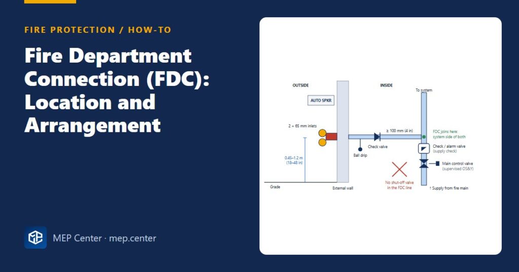
The fire department connection (FDC) is how the fire service pumps water into your sprinklers and standpipes when the building’s own supply is weak, has failed or has been shut off by mistake. An FDC hidden behind planting, fed into the wrong side of a valve or fitted with a shut-off valve can turn that backup into nothing. This is how to locate and arrange one so it works on the night it is needed.
Step by step: locating and arranging the FDC
- Agree the details with the local fire service first. This covers the inlet type (2½ in / 65 mm threaded or a large-diameter Storz-type coupling), the thread, the number of inlets and the preferred façade. Why: local rules usually govern the FDC, and a coupling that does not fit wastes the most important minutes.
- Choose the façade the appliance will arrive at. That is the street or fire access side, next to where the pumper can park. Why: the driver must see the FDC from the road, and hose runs from the appliance should be short.
- Keep it near a hydrant. A common fire code and recent NFPA 14 requirement is 30 m (100 ft) or less of hose lay from a hydrant. Why: the appliance draws from the hydrant and pumps into the FDC, so both hose lays must be short.
- Set the inlet height to 0.45–1.2 m (18–48 in) above the adjoining grade. Why: crews can connect and tighten couplings without kneeling or using ladders. Check the final landscaping levels, not the architectural datum.
- Decide the number of inlets. A common practice is one 2½ in inlet per 950 L/min (250 gpm) of system demand, with at least two. Why: each 65 mm hose carries a limited flow, so too few inlets means the system demand cannot be pumped in.
- Connect on the system side of the control valve and the supply check valve. On a wet system with an alarm valve, follow the valve maker’s arrangement. Why: the fire service can then feed the system even with the main control valve closed, and its water cannot run back into the public main.
- Fit a check valve and an automatic ball drip, and do not fit a shut-off valve. The ball drip goes between the check valve and the inlet. Why: the check keeps system water from spilling out of an uncapped inlet, the ball drip empties the exposed stub so it cannot freeze, and a valve in the line could be found closed.
- Size the FDC pipe to at least 100 mm (4 in). Go larger where the hydraulic check of the FDC supply case needs it. Why: the full system demand has to pass through this pipe with an inlet pressure the fire service can deliver. Many designs assume about 10.3 bar (150 psi) at the inlet, but confirm that with the fire service.
- Sign it. Use raised or engraved letters at least 25 mm (1 in) high naming the system (“AUTOMATIC SPRINKLERS”, “STANDPIPE”, or both). Where the FDC serves only part of a building or several buildings, the sign says which. Why: a crew facing three FDCs must know which one feeds the fire floor.
- Protect it and keep it clear. Use bollards where vehicles manoeuvre, and keep parking, bins and planting away from it. A waterflow bell above the FDC is common practice. Why: the bell shows the arriving crew which system is flowing.
Quick check: how many inlets?
Example: an office building with a sprinkler demand of 1600 L/min including hose allowance, served by one wet riser.
Inlets = 1600 ÷ 950 = 1.7 → round up to 2 × 65 mm inlets, which is also the usual minimum.
A combined sprinkler and standpipe system in a sprinklered building can need up to 3785 L/min (1000 gpm). At 950 L/min per inlet that is 3785 ÷ 950 = 4.0 → 4 inlets, or a single large-diameter inlet where the fire service uses one.
Typical values — verify with the edition adopted locally.
High-rise and multi-building sites
High-rise buildings usually need two or more FDCs, remote from each other, so that falling debris on one façade does not cut off the supply. Each pressure zone needs a way for the fire service to pump into it.
On campuses with a private main, a free-standing yard FDC near the road and a hydrant often works better than one on the building. Its underground pipe then follows the same rules as the main. See hydrant connection to the fire main and, for standpipe demands, standpipe classes I, II and III explained.
Common FDC mistakes
- The FDC connected below the main control valve, so it cannot feed the system when that valve is closed.
- A butterfly or gate valve “for maintenance” in the FDC line.
- No ball drip, so the stub freezes and splits in winter.
- An FDC on the back façade, behind a gate or 80 m from the nearest hydrant.
To check that the fire service inlet pressure can actually deliver your demand, carry the FDC case through your sprinkler hydraulic calculation.
Fire Protection & Suppression Systems Design (NFPA)
20 narrated modules with animated diagrams, two complete worked projects (DWG + DXF), the Fire Calc Workbook and an online calculator.
Modules 1–3 are free, no account needed · full course €15,00 one-time
FAQ
Where should the fire department connection be located?
On the street or fire access side of the building, clearly visible and unobstructed, typically within 30 m (100 ft) of a hydrant, with inlets 0.45–1.2 m (18–48 in) above grade. The local fire service has the final say.
Can an FDC line have a shut-off valve?
No, in normal practice there is no shut-off valve in the FDC line. It has a check valve and an automatic ball drip between the check valve and the inlet. Some editions allow a supervised valve at the connection to the system, so verify locally.
Which side of the control valve does the FDC connect to?
The system side of the main control valve and the supply check valve. The fire service can then still supply the sprinklers if the control valve has been closed, and its water cannot flow back into the public main.
How many inlets does an FDC need?
Local rules decide. A common practice is one 65 mm (2½ in) inlet per 950 L/min (250 gpm) of system demand, with a minimum of two, or a single large-diameter inlet where the fire service uses one.
More Fire Protection (Sprinklers, NFPA) articles
- 12 Common Sprinkler Design Mistakes Reviewers Reject
- ESFR Sprinklers: Quick Rules Before You Specify Them
- Fire Hose Cabinets and Hose Valves: EN 671 vs NFPA 14
- Sprinkler Hydraulic Calculation: A Step-by-Step Worked Example
- Backflow Preventers on Fire Lines: Losses and Layout
- Fire Pump Room Design Checklist