
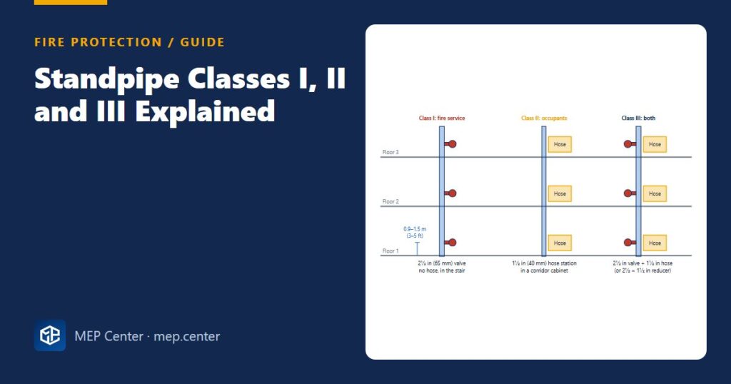
“Provide a standpipe system” is one line in a fire strategy, but it hides a decision that changes the riser size, the pump and the cabinets on every floor: which class? Class I, II and III systems serve different users with different hose sizes. Here is what each class means in NFPA 14 terms, and how the choice plays out on a project.
The three classes at a glance
| Class | User | Connection | Typical design point | Where you see it |
|---|---|---|---|---|
| I | Fire service, trained brigades | 2½ in (65 mm) hose valve, no hose | 500 gpm (1893 L/min) on the most remote standpipe, 100 psi (6.9 bar) at the remote outlet | Exit stairs of multi-storey and high-rise buildings, large floor plates |
| II | Trained occupants (first aid) | 1½ in (40 mm) hose on a rack or reel | 100 gpm (379 L/min) at 65 psi (4.5 bar) | Corridor hose cabinets, stages, special hazards |
| III | Both | 2½ in + 1½ in, or a 2½ in valve with a removable 2½ × 1½ in reducer | As Class I | Buildings where the owner wants in-house hose as well |
Occupant hose is declining. Many codes allow, or even prefer, omitting the 1½ in hose in fully sprinklered buildings, subject to the AHJ, because untrained people with hose lines delay evacuation. Many national regulations still demand a fire hose cabinet or hose reel on every floor alongside a Class I system for the fire service. Design both if required, and label which requirement each element answers to.
System types: where the water comes from
The class says who uses the outlet. The type says how water reaches it:
- Automatic wet: full of water and connected to a supply that meets the demand. This is the default for high-rise and combined sprinkler/standpipe risers.
- Automatic or semi-automatic dry: used for freezing areas such as open car parks and unheated stairs. Water must reach the outlet within about 3 minutes.
- Manual wet or manual dry: all of the demand comes from the fire service through the FDC. This is allowed only for Class I in non-high-rise buildings where the AHJ agrees.
Class II and Class III need an automatic or semi-automatic supply, because an occupant has no pump.
Where Class I outlets go
- In every required exit stair, at each floor. NFPA 14 defaults to the intermediate landing, while many building codes prefer the main floor landing. The AHJ decides, so show the choice on the drawings.
- On both sides of a horizontal exit, at exit passageway entrances, and on the roof or top landing of flat-roofed buildings.
- Extra outlets where any point on the floor is beyond the travel distance along the hose route: typically 45.7 m (150 ft) unsprinklered or 61 m (200 ft) sprinklered.
Class II stations cover every point within 39.7 m (130 ft) with 1½ in hose, or 36.6 m (120 ft) with smaller hose. All outlets sit 0.9–1.5 m (3–5 ft) above the floor.
Quick calc: Class I demand
Rule: 500 gpm (1893 L/min) for the most remote standpipe (250 gpm from each of its two most remote outlets), plus 250 gpm (946 L/min) for each additional standpipe. The total is capped at 1000 gpm (3785 L/min) in sprinklered buildings and 1250 gpm (4731 L/min) in unsprinklered ones. The duration is at least 30 minutes.
Sprinklered building, 4 stairs: 500 + 3 × 250 = 1250 gpm → capped at 1000 gpm (3785 L/min). Water for 30 min: 3785 × 30 = 113.6 m³.
Unsprinklered building, 3 stairs: 500 + 2 × 250 = 1000 gpm (3785 L/min), below the 1250 gpm cap.
In a sprinklered building with a combined riser, the standpipe demand usually includes the sprinkler demand. Run both cases and use the larger.
Pressure limits and pipe sizes
| Item | Typical NFPA 14 value |
|---|---|
| Minimum residual, most remote 2½ in outlet | 100 psi (6.9 bar) |
| Pressure-regulating device at 2½ in outlets | Where static exceeds 175 psi (12.1 bar), limit to 175 psi |
| 1½ in occupant outlets | Residual limited to 100 psi (6.9 bar) |
| Maximum anywhere in the system | 350 psi (24.1 bar), including churn and FDC pumping |
| Minimum standpipe size | 4 in (100 mm); 6 in (150 mm) for combined systems, or 4 in if fully sprinklered and hydraulically calculated |
Typical values — verify with the edition adopted locally.
Tall buildings are split into pressure zones so that the top outlet gets 100 psi without the bottom outlets exceeding the limits. The pump that delivers this is sized as in fire pump sizing to NFPA 20. Each zone also needs a way for the fire service to pump in; see FDC location and arrangement.
Fire Protection & Suppression Systems Design (NFPA)
20 narrated modules with animated diagrams, two complete worked projects (DWG + DXF), the Fire Calc Workbook and an online calculator.
Modules 1–3 are free, no account needed · full course €15,00 one-time
FAQ
What is the difference between Class I, II and III standpipes?
Class I has 2½ in (65 mm) hose valves for the fire service with no hose provided. Class II has 1½ in (40 mm) hose stations with hose for trained occupants. Class III combines both.
What pressure is required at a Class I standpipe outlet?
Typically 100 psi (6.9 bar) residual at the hydraulically most remote 2½ in outlet while the system demand flows. That demand is 500 gpm for the first standpipe plus 250 gpm for each additional one, up to the cap.
Can a Class II or III standpipe be manual?
No. Class II and Class III systems need an automatic or semi-automatic water supply, because occupants cannot pump water into the system. Manual systems are limited to Class I where the AHJ accepts them.
Where are Class I hose valves placed?
In every required exit stair at each floor level, on both sides of horizontal exits, and on the roof or top landing of flat-roofed buildings. Extra outlets are added where the hose-route travel distance exceeds the limit.
More Fire Protection (Sprinklers, NFPA) articles
- Sprinkler Spacing Rules: Areas, Wall Distances and Obstructions
- Wet Riser vs Dry Riser: Which Building Needs Which
- Fire Pump Room Design Checklist
- Fire Department Connection (FDC): Location and Arrangement
- Fire Pump Sizing to NFPA 20: Rated Point, Curve Checks and Jockey
- Sprinkler Obstruction Rules: A Quick Field Guide