
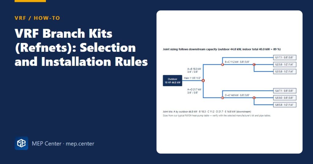
The refnet joint is a small Y-shaped fitting, but a wrong size or a joint lying on its side can starve half of a VRF system of refrigerant. Branch kits are selected from manufacturer tables, yet the logic behind those tables is the same everywhere — and so are the installation rules that site teams forget.
Refnet joint or header?
Refnet joints (Y-joints) split one gas/liquid pair into two and are placed in series along the route, building a tree. They follow corridors well and let you add a branch anywhere. Headers have one inlet and several outlets (typically 4, 6 or 8) and suit a compact group of units around one point, such as a hotel floor fed from a shaft. You can combine them: joints along the main route, a header at the end — but normally no further branching after a header outlet.
Selecting the kits step by step
- Fix the outdoor unit and the indoor units first. Our house rule: the indoor total is never more than 100 % of the outdoor capacity, we aim for about 90 %, and we step up one outdoor size above about 92 %. Why: joint sizes follow capacities, so they change if the selection changes.
- Draw the tree and name the joints. Label the first branch A, then B, C… along each route. Why: the kit schedule, the sizing table and the site drawings use the same letters.
- Size the first branch by the outdoor unit. Joint A takes the outdoor unit capacity class, matching the main pipe. Why: the main carries what the outdoor unit can deliver, not the indoor total.
- Size every other joint by downstream indoor capacity. Add the nominal kW of all indoor units fed through that joint and read the kit from the manufacturer’s table. Why: velocity and oil return depend on what actually flows through it.
- Size the pipes between joints the same way. A branch is never larger than the main. Why: a branch above the main size is only possible when the connection ratio is above 100 %, which our rule avoids anyway.
- Use the kit reducers. Kits come with reducers for the different pipe sizes they cover; cut them at the marked diameter. Why: site-made reductions disturb the flow split.
- Add the fittings to the equivalent length. A typical allowance is 0.5 m per joint and 1.0 m per header. Why: the farthest unit by equivalent length governs the length limits.
- Check the length after the first branch. Typically 40 m to the farthest indoor unit, extendable to 90 m with conditions. Why: putting joint A right next to the outdoor unit “to keep the main short” often breaks this limit.
Joint A: outdoor class 44.8 kW, main 1 1/8″ / 1/2″.
Joint B: 7.1 + 5.6 + 5.6 = 18.3 kW → pipe A→B 3/4″ / 3/8″ (16.1–22.4 kW band).
Joint C: 5.6 + 5.6 = 11.2 kW → B→C 5/8″ / 3/8″ (≤ 16 kW band).
Joint D: 7.1 + 9.0 + 5.6 = 21.7 kW → A→D 3/4″ / 3/8″.
Joint E: 9.0 + 5.6 = 14.6 kW → D→E 5/8″ / 3/8″.
Check: the downstream totals of B and D add up to 18.3 + 21.7 = 40.0 kW, the indoor total ✓.
Installation rules for joints
- Orientation: horizontal (both outlets at the same level) or vertical (outlets up or down), within the manufacturer’s tolerance — typically about ±15°.
- Straight run: typically at least 0.5 m of straight pipe before each joint, and the manufacturer’s minimum distance between consecutive joints and after a bend.
- Supports: within about 0.3–0.5 m of each joint, over the insulation; never let a joint carry pipe weight.
- Insulation: use the insulation shells supplied with the kit, seal all seams, gas and liquid insulated separately.
- Brazing: dry nitrogen flowing during brazing; joints brazed, flares only at indoor units.
- Access: show access panels at joints in fixed ceilings so they can be leak-checked.
Typical values — verify with the edition adopted locally and with the selected manufacturer’s installation manual.
For full pipe sizing and length limits, see VRF refrigerant piping design; for the connection ratio rule, VRF outdoor unit selection; and for the errors that cost most on site, 10 common VRF design mistakes.
VRF / VRV System Design
From room loads to a buildable VRF drawing set: unit selection, connection ratio, refrigerant piping, EN 378 checks and worked projects.
Modules 1–3 are free, no account needed · full course €10,00 one-time
FAQ
How do you select a VRF refnet joint?
The first branch after the outdoor unit is selected by the outdoor unit capacity. Every other joint is selected by the total nominal capacity of the indoor units downstream of it, using the manufacturer’s kit table.
Can a refnet joint be installed at an angle?
Only within the manufacturer’s tolerance, typically about ±15° from horizontal or vertical. A joint lying on its side sends more liquid to the lower outlet and starves the other branch.
Can I branch after a header?
Normally no. Most manufacturers do not allow further branching downstream of a header outlet, except where their manual explicitly permits it.
Can I use another manufacturer’s branch joint?
No. Use the outdoor unit manufacturer’s own joints and headers; they are designed for even oil and refrigerant distribution and are part of the system warranty.