
VRF refrigerant piping looks simple on a drawing – two lines and a few Y-joints – but most VRF site problems start here: undersized gas lines that eat capacity, oversized risers that stop oil returning, joints installed on their side, and a refrigerant charge nobody recalculated. This guide gives you the sizing logic, the limits to check, and a complete worked example with the additional charge.
- Size every branch on the total nominal capacity of the indoor units downstream of it.
- Size the main pipe (outdoor unit → first branch) on the outdoor unit capacity, not the indoor total.
- Check three lengths early: actual and equivalent length to the farthest unit, and length after the first branch (typically 40 m).
- If the equivalent length exceeds about 90 m, the gas main typically goes one size up – only to sizes the manufacturer permits.
- Additional charge = Σ liquid length × kg/m factor, rounded up to 0.1 kg. The total charge feeds the leak safety check.
- Brazing under nitrogen, 24 h nitrogen pressure test, deep vacuum below 500 microns, both lines insulated separately.
Topology: refnet joints, headers and segment names
A heat-pump VRF system connects one outdoor unit (or module group) to many indoor units with two pipes: a gas line (larger; suction vapour in cooling, hot discharge gas in heating) and a liquid line (smaller). Heat-recovery systems add a third pipe and branch selector boxes; the logic is the same, but use that system’s own tables.
- Refnet (Y) joints split one pipe pair into two and are placed in series along the corridor, forming a tree. This is the standard solution.
- Headers feed 4, 6 or 8 units from one point. Good for compact clusters; usually no further branching is allowed downstream of a header outlet.
Use the manufacturer’s own joints, mounted horizontally or vertically within tolerance (typically ±15°) with about 0.5 m of straight pipe upstream – a joint on its side starves one branch.
Vocabulary: the main pipe runs from the outdoor unit to the first branch; branch pipes run between joints; connection pipes feed each unit. Label every segment with an ID, gas/liquid size and length.
The sizing principle
Each segment is sized on the nominal capacity it feeds. Three rules complete it:
- The main follows the outdoor unit. Even at a 90 % connection ratio, the main carries what the outdoor unit can deliver.
- A branch is never larger than the main. If the downstream indoor total gives a bigger size (possible above 100 % ratio), use the main size.
- Indoor connection pipes match the unit’s connections, unless the manufacturer asks for an increase on long runs.
Why? Too small a gas line costs capacity through pressure drop; too large a gas line slows the vapour so much that oil no longer returns, especially in risers.
Typical sizes for R410A heat-pump systems
| Downstream indoor capacity | Gas line | Liquid line |
|---|---|---|
| ≤ 16.0 kW | 5/8″ (15.88 mm) | 3/8″ (9.52 mm) |
| 16.1–22.4 kW | 3/4″ (19.05 mm) | 3/8″ |
| 22.5–33.0 kW | 7/8″ (22.22 mm) | 3/8″ |
| 33.1–47.0 kW | 1 1/8″ (28.58 mm) | 1/2″ (12.70 mm) |
| 47.1–71.0 kW | 1 1/8″ | 5/8″ |
| 71.1–104 kW | 1 3/8″ (34.92 mm) | 3/4″ (19.05 mm) |
| 104.1–150 kW | 1 5/8″ (41.28 mm) | 3/4″ |
Main pipes by outdoor class (typical): 8 HP 3/4″/3/8″; 10 HP 7/8″/3/8″; 12–16 HP 1 1/8″/1/2″; 18–24 HP 1 1/8″/5/8″; 26–36 HP 1 3/8″/3/4″; 38–52 HP 1 5/8″/3/4″. Indoor connection pipes are typically 1/2″/1/4″ for 3.6–5.6 kW units and 5/8″/3/8″ for 7.1–16 kW units – always match the unit. Copper sizes are outside diameters. R32 and three-pipe heat-recovery systems use different sizes.
All sizes, limits, charge factors and test values here are typical — verify with the selected manufacturer’s installation manual and with the edition of any standard adopted locally.
Length and height limits
Limits protect oil return, refrigerant distribution and capacity. They vary widely between ranges, so treat these as planning values:
| Limit | Typical value |
|---|---|
| Actual length, outdoor → farthest indoor | 150–175 m (some ranges ~200 m) |
| Equivalent length, outdoor → farthest indoor | 175–190 m (some ranges ~225 m) |
| Total piping length (one line, not gas + liquid) | 300–1000 m, model-dependent |
| Height, outdoor above indoor | 50 m (more with options in some ranges) |
| Height, outdoor below indoor | 40 m (up to 90 m with options in some ranges) |
| Height between indoor units | 15–30 m |
| After first branch → farthest indoor | 40 m, extendable to 90 m with conditions |
The 40 m after-first-branch limit catches many designers: placing the first branch right next to the outdoor unit “to keep the main short” makes everything downstream too long. Extending it to 90 m typically requires upsized branches and limits on route-length differences.
With the outdoor unit above, the gas riser must lift oil (some manufacturers require oil traps); with it below, the liquid riser can flash. These limits often decide how the building is split, so check them at concept stage.
Equivalent length
Equivalent length adds an allowance for fittings to the actual length. Widely used allowances are 0.5 m per refnet joint and 1.0 m per header; elbows add roughly 0.2–0.7 m each depending on size. At early design, estimate equivalent length ≈ 1.2–1.3 × actual length. Check the two or three longest routes, not just the longest actual run.
If the equivalent length to the farthest unit exceeds about 90 m, increase the gas main one size (for example 1 1/8″ → 1 3/8″), only to a size the manufacturer lists as permitted. Never upsize a gas riser on your own judgement: lower velocity means poor oil return. Upsizing a liquid line also raises the charge.
Worked example: 45 kW system on two floors
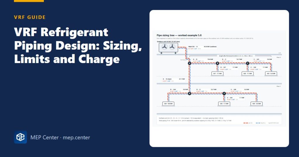
Inputs. Outdoor unit on the roof, nominal 45.0 kW from the selected model’s data (16 HP class). Floor 2: IU1 7.1 kW, IU2 7.1 kW, IU3 5.6 kW. Floor 1: IU4 9.0 kW, IU5 7.1 kW, IU6 5.6 kW. Σ indoor = 41.5 kW; connection ratio = 41.5 ÷ 45.0 = 92.2 % → 92 %, right at our step-up point, so the corrected-capacity check in the connection ratio guide must confirm it. Main 25 m to first branch A; A feeds joints B, C on floor 2 and, through a 4 m riser, joints D, E on floor 1.
Step 1 – downstream capacities and sizes.
| Segment | Downstream | kW | Gas / liquid | Length |
|---|---|---|---|---|
| Main OU → A | outdoor capacity | 45.0 | 1 1/8″ / 1/2″ | 25 m |
| A → B | IU1 + IU2 + IU3 | 7.1 + 7.1 + 5.6 = 19.8 | 3/4″ / 3/8″ | 8 m |
| B → C | IU2 + IU3 | 12.7 | 5/8″ / 3/8″ | 6 m |
| A → D (riser) | IU4 + IU5 + IU6 | 9.0 + 7.1 + 5.6 = 21.7 | 3/4″ / 3/8″ | 4 m |
| D → E | IU5 + IU6 | 12.7 | 5/8″ / 3/8″ | 7 m |
| To IU1, IU2, IU4, IU5 | 7.1–9.0 kW units | — | 5/8″ / 3/8″ | 4, 3, 5, 3 m |
| To IU3, IU6 | 5.6 kW units | — | 1/2″ / 1/4″ | 5, 4 m |
Step 2 – limits. Route to IU3 = 25 + 8 + 6 + 5 = 44 m; to IU6 = 25 + 4 + 7 + 4 = 40 m, so IU3 is farthest. Equivalent length ≈ 44 + 4.5 (elbows) + 3 joints × 0.5 = ≈ 50 m → below 90 m, no main upsizing. After first branch: 8 + 6 + 5 = 19 m ≤ 40 m ✓. Total piping = 25 + 8 + 4 + 6 + 3 + 5 + 4 + 5 + 7 + 3 + 4 = 74 m ✓. Outdoor about 8 m above floor 1 units ✓.
Step 3 – additional charge (typical R410A factors, liquid line only):
- 1/2″: main 25 m × 0.12 kg/m = 3.000 kg
- 3/8″: 8 + 4 + 6 + 3 + 4 + 5 + 7 + 3 = 40 m × 0.06 kg/m = 2.400 kg
- 1/4″: 5 + 4 = 9 m × 0.022 kg/m = 0.198 kg
- Total = 5.598 kg → round up to 5.6 kg
Sanity check. Liquid lengths 25 + 40 + 9 = 74 m = total piping length ✓ (every segment has one liquid line). Joint A is selected from the outdoor capacity range (45 kW), B and D from 19.8 and 21.7 kW, C and E from 12.7 kW, using the manufacturer’s kit table.
Additional refrigerant charge
The outdoor unit ships with a factory charge for itself and a short reference pipe. The installer adds charge for the site piping, almost entirely in the liquid line:
Additional charge = Σ (Lliquid,d × fd) [+ any fixed additions the manufacturer specifies]
Lliquid,d is the liquid line length (m) of diameter d and fd the charge factor (kg/m). Typical R410A factors: 1/4″ 0.022, 3/8″ 0.06, 1/2″ 0.12, 5/8″ 0.18, 3/4″ 0.27, 7/8″ 0.37 kg/m. Round up to 0.1 kg. Write factory, additional and total charge on the outdoor unit label and the commissioning sheet – the total is what the refrigerant leak safety check uses. Recalculate with as-built lengths; charge by weight as liquid, never “by pressure”.
Material, brazing, testing and insulation
Copper
Use refrigeration-grade copper (cleaned, capped, dry) to EN 12735-1 or the local equivalent – never plumbing tube. Annealed (soft) tube up to 5/8″; half-hard from 3/4″ up. Typical minimum walls for R410A run from 0.8 mm (up to 1/2″) to 1.4–1.45 mm (1 5/8″). Braze throughout; flares only at indoor unit connections, with R410A flare dimensions, correct torque and an access panel.
Brazing, pressure test, vacuum
- Nitrogen purge while brazing at very low flow (≈ 0.02 MPa) – otherwise oxide scale blocks expansion valves within months.
- Pressure test with dry nitrogen only, in steps, up to the design pressure – typically 4.0–4.15 MPa gauge (40–41.5 bar). Hold 24 h; correct about 0.01 MPa per 1 K temperature change. Outdoor service valves stay closed.
- Evacuation to a deep vacuum, typically below 500 microns (≈ 67 Pa abs), then a standing test of 30–60 min. A rising reading means a leak or moisture.
Insulation and supports
Insulate gas and liquid lines separately over their whole length, including joints and flares, with closed-cell insulation rated ≥ 120 °C (never below 100 °C) for the hot gas in heating. Typical thickness: 13 mm up to 5/8″ and 19 mm for 3/4″–1 5/8″ in normal ceilings; 19/25 mm in humid spaces. Support over the insulation with load-bearing inserts, with a support near every joint, bend and flare. Never core through columns or through beams without structural approval.
Pipe sizes depend on the outdoor selection – see our guide on VRF connection ratio and outdoor unit selection – and the indoor capacities come from your cooling load calculation.
Common mistakes
- Sizing a branch on the outdoor capacity, or the main on the indoor total.
- Placing the first branch next to the outdoor unit and blowing the 40 m after-first-branch limit.
- Upsizing a gas riser without the manufacturer’s approval – oil return fails.
- Additional charge calculated from design drawings and never updated to as-built lengths.
- No nitrogen during brazing; pressure test with compressed air (moisture).
Quick checklist
- Every segment labelled with ID, downstream kW, gas/liquid size and length.
- Main sized on outdoor capacity; no branch larger than the main.
- Actual, equivalent and after-first-branch lengths checked on the two or three longest routes.
- Height differences checked (outdoor above/below, indoor to indoor).
- Gas main upsized only if equivalent length > ~90 m and the size is permitted.
- Additional and total charge calculated and passed to the leak safety check.
VRF / VRV System Design
From room loads to a buildable VRF drawing set: unit selection, connection ratio, refrigerant piping, EN 378 checks and worked projects.
Modules 1–3 are free, no account needed · full course €10,00 one-time
FAQ
How do you size VRF refrigerant pipes?
Size each branch on the total nominal capacity of the indoor units downstream of it, and the main pipe on the outdoor unit capacity. Then check length limits and use the manufacturer’s table for the final sizes.
What is the maximum pipe length after the first branch?
Typically 40 m to the farthest indoor unit, extendable to about 90 m when the manufacturer’s conditions are met, such as upsizing the branch pipes. Check the exact rule of the selected range.
When should the gas main be upsized?
Typically when the equivalent length to the farthest indoor unit exceeds about 90 m. Go one size up only to a size the manufacturer permits, because an oversized gas riser can stop oil returning.
How is the additional refrigerant charge calculated?
Multiply each liquid line length by its kg-per-metre factor, add any fixed amounts the manufacturer specifies, and round up to 0.1 kg. For R410A typical factors are 0.022 kg/m for 1/4″, 0.06 for 3/8″ and 0.12 for 1/2″.