
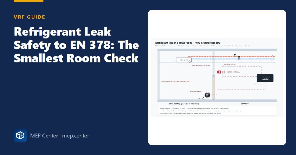
A VRF system holds one shared refrigerant charge – often 20–40 kg – and if a joint fails inside one room, much of that charge can end up in that room. EN 378 therefore asks a deliberately pessimistic question: if the whole charge leaks into the smallest room the system serves, does the concentration stay below a safe limit? This guide shows you how to run that check in five minutes, what to do when a room fails, and why R32 changes the rules.
- The smallest occupied room on a system governs – never the largest.
- Check: total system charge ÷ room volume ≤ practical limit. For R410A the EN 378-1 practical limit is 0.44 kg/m³.
- Work backwards: Vmin = charge ÷ limit gives the smallest room the system may serve – scan the plan with that one number.
- Count only the volume the gas can really reach: clear height, no voids above closed ceilings, no rooms behind doors.
- Fixes in order of preference: remove the unit, serve the room from a smaller system, split the system, add a permanent low-level opening, and only then detection, shut-off valves or ventilation.
- R32 (A2L) is flammability-governed and far stricter: practical limit 0.061 kg/m³.
Why the smallest room governs
Outdoor unit, mains, branch kits and every indoor unit share one circuit. If a flare joint fails in a 7.5 m² store room, refrigerant from both sides of the leak can flow out there until pressures equalise or someone isolates the system. For R410A the hazard is not fire – it is non-flammable and of low toxicity – but oxygen displacement and cardiac sensitisation. The vapour is about 2.5 times denser than air and collects at low level, so a person working or sleeping in a small closed room can be exposed before noticing anything.
The problem is never the big room; it is the store room, single office, meeting booth, security cabin or hotel bathroom that someone “just added” to a 30 kg system because a branch pipe passed nearby. Find those rooms before the piping layout is fixed – this check decides how systems are split.
The standards and the limits you need
Three documents share the same idea: EN 378 (Europe and many EN-adopting countries; “practical limit”, PL), ISO 5149 (international base text; “refrigerant concentration limit”, RCL) and ASHRAE 15/34 (North America; RCL). Typical values for VRF:
| Refrigerant | Safety group | Practical limit (EN 378-1) | What governs |
|---|---|---|---|
| R410A | A1 – non-flammable | 0.44 kg/m³ | Toxicity / oxygen deprivation (ATEL/ODL 0.42 kg/m³) |
| R32 | A2L – mildly flammable | 0.061 kg/m³ (= 0.2 × LFL) | Flammability (LFL 0.307 kg/m³) |
ASHRAE 15/34 uses an RCL of about 0.42 kg/m³ (26 lb per 1000 ft³) for R410A and halves it for institutional occupancies such as hospitals. The differences are small but real – write the standard and edition on the drawing.
The limits and charge factors in this article are typical values as tabulated in EN 378-1:2016 and in our VRF course — verify with the edition adopted locally, any national variation, and the selected manufacturer’s data.
EN 378 also classifies buildings by occupancy category (a – general, e.g. hotels, hospitals, schools, shops; b – supervised, e.g. offices; c – authorised persons only) and location class (where the refrigerant-containing parts are). A VRF serving rooms is in practice location class I or II. The standard grants relaxations for some combinations, but in comfort cooling designers normally apply the plain check to every room and treat relaxations as a last resort – today’s archive becomes tomorrow’s office.
The five-step check
- Total system charge m (kg) = factory charge of all outdoor modules + additional charge from the drawn liquid lines.
- List every room served by the system. A room served by two systems is checked against each (conservatively the larger charge).
- Find the smallest room by volume, not by floor area – a low suspended ceiling can make a bigger room fail.
- Concentration: C = m ÷ V, where C is in kg/m³, m is the total charge in kg and V the room volume in m³.
- Compare: C ≤ PL → pass and record. C > PL → choose a solution and re-check.
The fast way: compute Vmin = m ÷ PL once per system, divide by the ceiling height, and mark every room on the plan smaller than that floor area.
Total charge: factory plus additional
The total charge is not known until the piping is drawn, which is why the check is repeated after piping design. Additional charge is calculated from liquid line lengths (typical R410A factors: 1/4″ 0.022, 3/8″ 0.06, 1/2″ 0.12, 5/8″ 0.18 kg/m), rounded up to 0.1 kg. For concept stage, an R410A system in a mid-rise building typically holds roughly 0.3–0.6 kg per kW of outdoor cooling capacity – an indicative range only, to spot problems early. Our VRF refrigerant piping design guide shows the full charge calculation.
Room volume: what you may and may not count
- Count: floor area × clear height to the underside of the suspended ceiling.
- Do not count: the void above a closed tile ceiling, raised-floor voids, shafts, and adjacent rooms behind doors – even doors “always open”.
- Connected spaces may be added only through permanent openings that cannot be closed, of sufficient free area and at low level, because the heavy gas moves along the floor. Take the minimum area and height from the edition in force; a door undercut does not qualify.
- Basements: heavy gas has nowhere to go and several relaxations do not apply below ground. Avoid serving small basement rooms from large systems.
Worked example: the store room that fails
Inputs. System VRF-1, R410A, 56 kW (20 HP class) outdoor unit. Liquid lines: 50 m of 5/8″, 30 m of 1/2″, 130 m of 3/8″, 18 m of 1/4″. Factory charge 11.5 kg. Smallest room: store, 3.0 × 2.5 m, clear height 2.7 m under a closed tile ceiling, with a 2.2 kW wall unit added late. Office building, PL = 0.44 kg/m³.
Step 1 – additional charge. 50 × 0.18 = 9.000; 30 × 0.12 = 3.600; 130 × 0.06 = 7.800; 18 × 0.022 = 0.396. Sum = 20.796 kg → rounded up 20.8 kg.
Step 2 – total charge. m = 20.8 + 11.5 = 32.3 kg.
Step 3 – room volume. V = 3.0 × 2.5 × 2.7 = 20.25 m³.
Step 4 – concentration. C = 32.3 ÷ 20.25 = 1.60 kg/m³ > 0.44 → fails, by more than 3.5 times.
Step 5 – what the room could accept. mmax = 0.44 × 20.25 = 8.9 kg. And the smallest room this system may serve: Vmin = 32.3 ÷ 0.44 = 73.4 m³ → at 2.7 m, about 27.2 m². The store room is less than a third of that.
Fix options.
- Remove the unit and ventilate the store – cheapest, and often enough.
- Dedicated small split with 1.5–2.5 kg charge: C = 1.5 ÷ 20.25 to 2.5 ÷ 20.25 = 0.07–0.12 kg/m³ → pass.
- Permanent low-level opening to the corridor (12 × 3.0 × 2.7 = 97.2 m³): V = 20.25 + 97.2 = 117.45 m³ → C = 32.3 ÷ 117.45 = 0.28 kg/m³ → pass, if fire and acoustic strategy allow it.
Sanity check. 32.3 kg ÷ 56 kW ≈ 0.58 kg/kW – inside the typical 0.3–0.6 kg/kW planning range, so the charge is plausible. And 1.60 ÷ 0.44 = 3.6 ✓ (more than 3.5 times the limit).
Solutions when a room fails
1. Don’t serve it from the large system. Store rooms, cleaners’ rooms, small WCs and lift lobbies rarely need a VRF unit. Transfer air or add an extract fan.
2. Use a separate small system – a single split or mini-VRF whose total charge passes.
3. Split the large system so each part’s charge passes for its own smallest room. This often matches good practice anyway: one system per floor, shorter pipes, smaller charge. When you re-select outdoor units, keep our connection ratio rule in mind.
4. Permanent low-level opening to a larger space, agreed with the architect and fire engineer. Show it on the coordination drawings so nobody fits a door later.
5. Additional measures: a low-level detector that raises an alarm and closes automatic shut-off valves outside the room, or starts mechanical extract sized to keep the concentration below the limit. Read EN 378-1 Annex C and EN 378-3 (and IEC 60335-2-40 for A2L products) before relying on them; they bring calibration and testing obligations for the owner.
6. Change the system type for sensitive buildings with many small rooms – a water-based system avoids the problem altogether.
Leak detection, valves and plant enclosures
- Detectors at low level (commonly within about 0.3 m of the floor), near the unit and joints, out of supply air jets. Two stages (pre-alarm, main alarm) are common; set points per EN 378-3 and EN 50676.
- Calibration and testing at least annually is the usual requirement – write it into the O&M documents. An uncalibrated detector gives false confidence.
- Outdoor units in enclosures: a roofed, louvred room may become a machinery room under EN 378-3 (ventilation, detection, signage). Keep heavy-gas sources away from low-level openings into occupied spaces and AHU intakes.
R32 and other A2L refrigerants: a different logic
For A2L refrigerants the limit is set by flammability. With the simple practical limit, our 20.25 m³ store room would accept only 20.25 × 0.061 ≈ 1.2 kg of R32. EN 378-1 Annex C and IEC 60335-2-40 also give a comfort-application formula that depends on release height and floor area:
mmax = 2.5 × LFL5/4 × h0 × A1/2
mmax is the allowed charge (kg), LFL the lower flammability limit (kg/m³; 0.307 for R32), h0 the release height factor (typically 0.6 m floor-standing, 1.8 m wall, 2.2 m ceiling units) and A the floor area (m²). For a ceiling cassette in the 7.5 m² store: 2.5 × 0.229 × 2.2 × 2.74 ≈ 3.4 kg – still far below a large VRF charge. Newer product standards allow much larger charges when certified measures (detection, circulation airflow, shut-off valves) are built in, so for R32 run the manufacturer’s room-by-room check and the check required by your authority, and keep both in the file.
Common mistakes
- Checking the largest or “typical” room instead of the smallest by volume.
- Using only the indoor unit’s own charge – the whole system can discharge through one leak.
- Running the check at concept stage and never repeating it after piping or as-built charge changes.
- Counting the ceiling void or a neighbouring room behind a door.
- Arguing “nobody sits in a store room” without checking the standard and the client’s use.
- Specifying detectors and valves with no maintenance and calibration requirement.
Quick checklist
- Standard, edition and national variation written in the design basis.
- Refrigerant and safety group stated (A1 / A2L); occupancy category identified.
- Total charge per system = factory + additional, from the drawn liquid lines.
- Vmin calculated per system; every room listed; smallest volume found.
- Volumes use clear height; voids and rooms behind doors excluded.
- Every failing room resolved and re-checked.
- Detectors, valves, alarms and openings shown on the drawings; calibration in O&M.
- Safety table in the report and general notes: system, charge, room, volume, C, limit, result.
VRF / VRV System Design
From room loads to a buildable VRF drawing set: unit selection, connection ratio, refrigerant piping, EN 378 checks and worked projects.
Modules 1–3 are free, no account needed · full course €10,00 one-time
FAQ
What is the EN 378 practical limit for R410A?
EN 378-1:2016 tabulates 0.44 kg/m³ for R410A. Divide the total system charge by the volume of the smallest room served; the result must not exceed that limit unless additional measures are applied.
Why do you use the whole system charge and not the indoor unit charge?
All units share one circuit, so a leak in one room can release refrigerant from the whole system until pressures equalise or the system is isolated. The standard assumes that worst case.
Can I add the corridor volume to a small room?
Only through a permanent, non-closable opening of sufficient free area at low level. A door, even one normally kept open, does not count.
Is R32 easier or harder to approve than R410A?
Harder in the simple check: its practical limit is 0.061 kg/m³ because it is mildly flammable. Large R32 systems rely on certified built-in safety measures, so the manufacturer’s room-by-room check becomes part of the design.