
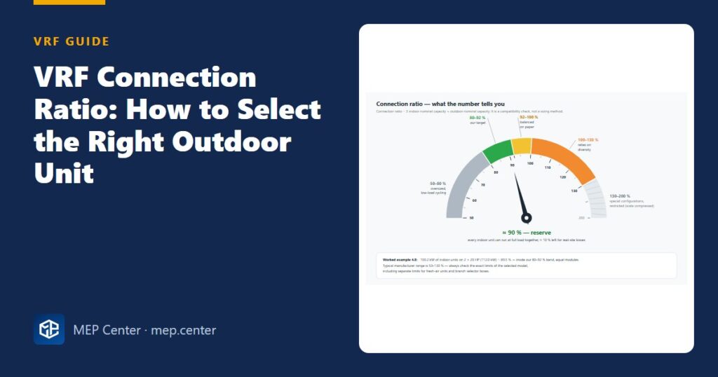
Every VRF catalogue says the connection ratio can go up to 130 %, so why do so many systems sized that way leave the top-floor west offices at 27 °C every July? Because the connection ratio only tells you whether a combination is allowed – not whether the outdoor unit will actually cover the load on site. This guide shows you how to read the ratio, the conservative rule we use in our own designs, and a full worked selection you can copy.
- Connection ratio = Σ indoor nominal capacity ÷ outdoor nominal capacity. It is a compatibility check, not a sizing method.
- Manufacturers typically allow 50–130 %. Our design default is stricter: the outdoor unit is never nominally smaller than the connected indoor total (ratio ≤ 100 %).
- Pick the smallest outdoor unit or combination that covers the indoor total; we aim for about 90 % and step up one size if the ratio rounds above 92 %.
- Then prove it: corrected capacity (outdoor temperature × pipe length × indoor wet bulb) must cover the block load with a sensible margin.
- Multi-module outdoor units: modules equal or at most one size step apart (20 + 22 HP yes, 30 + 14 HP no).
- Every change in outdoor size changes the electrical data: cable, breaker, board demand, generator.
What the connection ratio actually measures
The connection ratio (also called combination ratio or capacity ratio) compares two catalogue numbers:
Connection ratio = Σ Qindoor,nom ÷ Qoutdoor,nom × 100 %
Σ Qindoor,nom is the sum of the nominal cooling capacities (kW) of all indoor units connected to one refrigerant circuit. Qoutdoor,nom is the nominal cooling capacity (kW) of the outdoor unit or module combination. Both are values at standard rating conditions – not your calculated room loads.
Outdoor units are sold in horsepower (HP) classes. The HP label is a commercial size, not shaft power. A typical mapping is ≈ 2.8 kW cooling per HP; heating is roughly 3.1–3.2 kW per HP. Use the exact figures of the selected model.
| Outdoor class | Nominal cooling (typical, 2.8 kW/HP) |
|---|---|
| 16 HP | 44.8 kW |
| 18 HP | 50.4 kW |
| 20 HP | 56.0 kW |
| 22 HP | 61.6 kW |
Manufacturer limits versus our design rule
A typical published range is 50–130 %; systems with fresh-air units are often narrower, and a few special configurations go higher with restrictions. The lower limit exists because an inverter compressor cannot turn down to zero: a hugely oversized outdoor unit cycles and struggles with oil return.
Here is what the numbers mean physically:
- 90 % – every indoor unit can run at full load at the same time, with roughly 10 % nominal reserve for real-site losses.
- 100 % – balanced on paper only. After site corrections the true capacity is typically 5–15 % lower, so a 100 % system already leans on diversity.
- 110 % – diversity assumed. Works only if the rooms never all peak together.
- 130 % – about a quarter of the indoor capacity must never run with the rest. A documented bet, sometimes legitimate in hotels or schools.
Our rule, in one paragraph
For normal comfort projects – offices, public buildings, service buildings – the outdoor unit is never nominally smaller than the connected indoor total. Start with the smallest outdoor unit or module combination that covers the indoor total. If the resulting ratio rounds (to the whole percent) above about 92 %, go one size step up, and repeat until it doesn’t. Then confirm with the corrected capacity check below; that check can push you up again, never down.
Why so strict? Systems that underperform were nearly always sized at 110–130 % on paper and then met long risers, 40–46 °C roof air, dirty coils, defrost and growing loads. One size step costs little compared with a building that cannot hold temperature. We deviate deliberately only where real diversity exists – hotels, residential, heat-recovery systems with simultaneous heating and cooling – and then we write the assumption on the drawings.
Diversity: block load versus sum of peaks
Each room load is calculated at the hour when that room peaks. East rooms peak around 08:00–10:00, west rooms around 15:00–17:00, interior zones stay nearly flat. The outdoor unit sees the block load – the highest combined hourly load – which is lower than the sum of room peaks.
Diversity factor = block load ÷ Σ room peak loads
Short example: east rooms 40 kW (peak 10:00), west rooms 40 kW (peak 16:00), interior 20 kW. At 10:00 the west rooms carry about 26 kW; at 16:00 the east rooms carry about 27 kW. Block at 10:00 = 40 + 26 + 20 = 86 kW; at 16:00 = 27 + 40 + 20 = 87 kW. Diversity = 87 ÷ 100 ≈ 0.87. Take the block load from an hourly calculation whenever you can; rough office values are 0.80–0.90 for two opposite façades and 0.90–0.95 for one glazed façade.
Two warnings: never apply diversity twice (once in the block load and again by pushing the ratio to 130 %), and remember that heating has almost no diversity during morning warm-up.
Corrected capacity: what the outdoor unit really delivers
Nominal capacity is measured at 35 °C outdoor dry bulb, 19 °C indoor wet bulb and a short reference pipe. On your roof it is less:
Qcorr = Qnom × foutdoor × findoor WB × fpipe
Each f is a dimensionless factor from manufacturer data. Typical cooling values:
| Parameter | Condition | Typical cooling factor |
|---|---|---|
| Outdoor coil-inlet temperature | 35 / 40 / 43 / 46 °C | 1.00 / 0.95 / 0.92 / 0.88 |
| Indoor wet bulb | 17 / 19 / 22 °C WB | 0.91 / 1.00 / 1.10 |
| Equivalent pipe length | 60 / 90 / 100 m | ≈ 0.94 / ≈ 0.91 / ≈ 0.88–0.90 |
Use the coil-inlet temperature – a walled roof well can add 3–6 K. Factors multiply – 0.95 × 0.91 = 0.86, so a nominal 100 kW unit delivers 86 kW. Heating is checked separately with the design wet bulb and a defrost factor; in cold climates heating often decides the outdoor size.
All capacities, correction factors and limits in this article are typical values — verify with the selected manufacturer’s data and with the edition of any standard adopted locally.
Worked example: choosing the outdoor unit for one office floor
Inputs
- 18 indoor units, Σ indoor nominal = 100.2 kW
- Hourly calculation: Σ room peaks = 96 kW, block load = 88 kW (diversity 88 ÷ 96 = 0.92)
- Roof units, design coil-inlet temperature 40 °C → f = 0.95
- Equivalent length to farthest indoor unit ≈ 90 m → f = 0.91
- Combined factor: 0.95 × 0.91 = 0.8645; typical 2.8 kW/HP
Step 1 – smallest combination that covers the indoor total. 2 × 18 HP = 2 × 50.4 = 100.8 kW ≥ 100.2 kW. Ratio = 100.2 ÷ 100.8 = 99.4 % → rounds to 99 %, above 92 % → step up.
Step 2 – one step up. 18 + 20 HP = 50.4 + 56.0 = 106.4 kW. Ratio = 100.2 ÷ 106.4 = 94.2 % → 94 %, still above 92 % → step up.
Step 3 – next step. 2 × 20 HP = 112.0 kW. Ratio = 100.2 ÷ 112.0 = 89.5 % → 89 % ✓ (≤ 92 %). Modules equal ✓.
Step 4 – corrected capacity check.
| Option | Nominal | Ratio | Corrected (× 0.8645) | vs 88 kW block |
|---|---|---|---|---|
| 2 × 18 HP | 100.8 kW | 99.4 % | 87.1 kW | −0.9 kW — short |
| 18 + 20 HP | 106.4 kW | 94.2 % | 92.0 kW | +4.0 kW (+4.5 %) |
| 2 × 20 HP | 112.0 kW | 89.5 % | 96.8 kW | +8.8 kW (+10 %) |
Result: 2 × 20 HP. Note that 2 × 18 HP sits comfortably inside a 50–130 % catalogue range, yet after corrections it cannot even cover the block load. 18 + 20 HP covers it, but a 4.5 % margin disappears with the first seasons of coil fouling.
Sanity check. 96.8 ÷ 112 = 0.864 ✓ (matches the combined factor). Margin 8.8 ÷ 88 = 10 %. Same procedure for the floor above with Σ indoor = 93.2 kW, block load 80 kW and 60 m equivalent length (factor 0.95 × 0.94 = 0.893): 2 × 18 HP gives 93.2 ÷ 100.8 = 92.46 % → 92 % (at the edge, not above) and 100.8 × 0.893 = 90.0 kW, a 12.5 % margin over 80 kW. No reason to spend more there.
Multi-module outdoor units: equal or one step apart
Large capacities are built from two to four modules on the manufacturer’s header kit. A 40 HP system might be offered as 20 + 20, 18 + 22 or 16 + 24 HP. Our practice: modules are equal, or at most one size step apart (20 + 22, 22 + 24). Very unequal pairs like 30 + 14 HP are not acceptable even when the catalogue lists them.
- Backup: with 20 + 20 you keep 50 % if one module fails; with 30 + 14 you keep 68 % or only 32 %.
- Wear: the small module cycles, the large one carries the base load, and they age differently.
Upsizing changes the electrical design
Going from 2 × 18 to 2 × 20 HP typically adds about 3–5 kW of rated electrical input in total (check the selected model). Whenever an outdoor selection changes, issue an updated electrical data table: model, rated input, maximum running current, recommended protective device and supply cable per module. Also check main board demand, generator kVA, power-factor correction and the RCD type the manufacturer specifies.
Before you size: split the building into systems
Decide which rooms share a circuit before choosing any outdoor unit. Per floor is the usual choice; tenants get their own systems. Piping limits (see our VRF refrigerant piping design guide) and refrigerant charge in the smallest room (see the refrigerant leak safety check) can force a split. Critical rooms such as server rooms get dedicated duty/standby units.
Your inputs come from the room loads – if you need a refresher, read our cooling load calculation basics.
Common mistakes
- Treating “the ratio is inside 50–130 %” as proof that the system is big enough.
- Comparing nominal outdoor capacity with the block load without applying temperature and pipe-length corrections.
- Using the weather-file temperature instead of the coil-inlet temperature in a roof well.
- Applying diversity twice: in the block load and again by running the ratio at 120–130 %.
- Forgetting the heating check – warm-up has almost no diversity and defrost cuts capacity.
Quick checklist
- Rooms grouped into systems and the grouping shown on a system diagram.
- Σ indoor nominal capacity calculated from the selected models.
- Block load from an hourly calculation (or a documented diversity estimate).
- Coil-inlet temperatures and equivalent length defined.
- Ratio ≤ 100 %, target ≈ 90 %, stepped up if it rounds above 92 %.
- Corrected cooling and heating capacity ≥ block load with margin.
- Modules equal or one step apart.
- Electrical data table updated and sent.
VRF / VRV System Design
From room loads to a buildable VRF drawing set: unit selection, connection ratio, refrigerant piping, EN 378 checks and worked projects.
Modules 1–3 are free, no account needed · full course €10,00 one-time
FAQ
What is a good VRF connection ratio?
Manufacturers typically allow 50–130 %, but for normal comfort buildings we design at or below 100 % and aim for about 90 %. That leaves roughly 10 % reserve for long pipes, hot roofs and coil fouling.
Is a 130 % connection ratio wrong?
Not automatically — it is permitted by many manufacturers. It assumes about a quarter of the indoor capacity never runs with the rest, which can be true in hotels or schools but must be proven and documented.
Should I size the outdoor unit on the indoor total or on the block load?
Both. The indoor total sets the connection ratio; the corrected outdoor capacity must then cover the block load. The second check can only push the selection up, never down.
Can I combine a 30 HP and a 14 HP module?
Some catalogues allow it, but in our practice modules are equal or at most one size step apart. Unequal modules wear unevenly and lose most of their capacity if the larger one fails.