
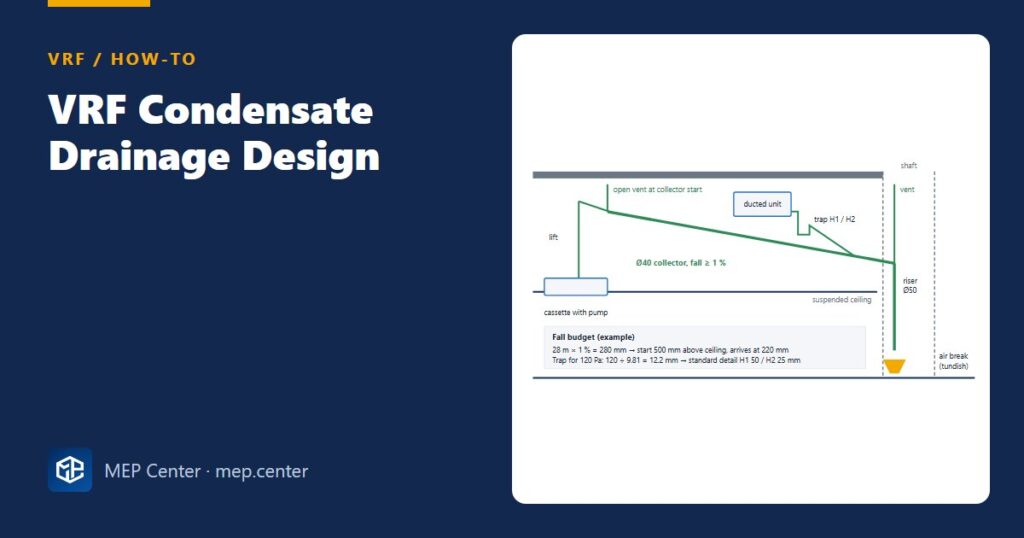
Most complaints in the first summer of a VRF installation are drain complaints, not refrigerant complaints: a cassette that stops on its float switch, a stained ceiling tile, a smell of sewer in a meeting room. Almost all of them start on the drawing, where the drain was a line with no levels.
Step by step
- Estimate the water. 1 kW of latent load ≈ 1.47 L/h of condensate (3600 ÷ 2450). Why: flows are small, so diameters are chosen for reliability against slime and air locks, not for capacity.
- Choose material. PVC-U, PP or PE-HD drainage pipe, long-radius bends, with a short manufacturer hose only at the unit. Why: copper and steel corrode in slightly acidic condensate; long transparent hoses grow algae.
- Size the pipes. Unit connection typically 32 mm OD for cassettes and ducted units; collector 40 mm up to about 70 kW connected, 50 mm for about 70–180 kW, 63 mm above that or for multi-floor risers. Never reduce downstream. Why: the step from 32 to 40 mm costs little and buys a margin against blockage.
- Check the fall budget. Fall = length × slope; at least 1 %, 1.5–2 % on short branches. Do it when you place the indoor units. Why: 30 m at 1 % already uses 300 mm of the void, and a beam can end the route.
- Design pump lifts correctly. Lift vertically within about 300 mm of the unit, stay 100–150 mm below the manufacturer’s maximum lift (typically 500–850 mm for cassettes), then fall continuously. One high point per unit. Why: a long horizontal run before the high point and shared lifts send water back into the pan.
- Trap every ducted unit with a negative-pressure pan. H1 > suction in mm w.c. (1 mm ≈ 9.81 Pa), H2 ≈ ½ H1, trap at the unit with a cleaning plug, never two traps in series. Why: without a seal the fan sucks air up the drain and the pan overflows.
- Connect branches from the top or side at 45°, never from below or with a 90° tee against the flow. Why: bottom connections fill from the collector and back up.
- Add vents and cleaning points. Open vent at the start of each collector (above the highest outlet or lift point) and at riser tops; cleaning points at starts, bends, riser bases and every 10–15 m. Why: pumped slugs of water siphon traps and slime builds up.
- Insulate drains in ceiling voids and conditioned spaces, including traps and lift sections, with closed-cell insulation of typically at least 10 mm, often 10–13 mm. Why: water at 12–15 °C makes the pipe sweat in a warm void.
- Discharge through an air break. Dedicated condensate riser to a tundish or trapped gully at the lowest level; split units in server rooms to the nearest rainwater downpipe. Why: condensate traps dry out in winter, and a direct soil connection then vents sewer air into the room.
Worked example
Office floor, cooling load 60 kW at SHR 0.75, ceiling void 600 mm, collector 28 m from the farthest unit to the shaft, one ducted unit with ESP 120 Pa.
Water: latent 60 × (1 − 0.75) = 15 kW → 15 × 1.47 = 22 L/h. Tiny — the pipe is sized for reliability.
Collector size: 60 kW connected → 40 mm (15–70 kW band); riser 50 mm.
Fall budget: highest practical collector level 500 mm above the ceiling (room for hangers). 28 m × 1 % = 280 mm → arrives at 500 − 280 = 220 mm above the ceiling. Feasible. A 450 mm downstand beam on the route would leave only 150 mm below it — reroute or plan a sleeve with the structural engineer.
Trap: 120 Pa ÷ 9.81 = 12.2 mm w.c. → minimum H1 about 20 mm, H2 about 10 mm. Our standard detail uses H1 ≈ 50 mm, H2 ≈ 25 mm where the outlet height allows; it survives evaporation in winter and a higher ESP set at commissioning.
Sanity check: no section rises except the cassette lift, every branch enters the collector at 45° from above, and the riser ends in a tundish.
Typical values — verify with the edition adopted locally and with the selected manufacturer’s drain table.
Supports and drawings
Plastic drains sag between supports and create counter-slopes. Pipe manufacturers’ guidance typically gives about 0.5 m for 32 and 40 mm and 0.6 m for 50 mm horizontally; indoor unit manuals often quote 1–1.5 m as an absolute maximum — use the closer spacing. On the drawing, show the drain in its own colour and layer with slope arrows (“i = 1 %”), diameters, invert levels at collector starts, level changes and the riser, plus trap, pump lift, cleaning point and air break details, and a riser diagram when several floors connect.
For the trap logic on larger units, see condensate drain trap design; for the other drawing-review items, common VRF design mistakes; and for the pipes the drain runs next to, refrigerant pipe insulation thickness.
VRF / VRV System Design
From room loads to a buildable VRF drawing set: unit selection, connection ratio, refrigerant piping, EN 378 checks and worked projects.
Modules 1–3 are free, no account needed · full course €10,00 one-time
FAQ
What slope does a VRF condensate drain need?
At least 1 % (1:100) continuous fall from the unit to the riser, with 1.5–2 % preferred on short branches. The only upward section allowed is the vertical lift right after a condensate pump.
What size should a VRF condensate collector be?
Typically 40 mm once more than two or three units connect (up to about 70 kW), 50 mm for about 70–180 kW and 63 mm above that or for risers serving several floors, never reducing downstream. Check the manufacturer’s drain table.
Can I connect a condensate drain directly to a soil stack?
No. Condensate flows only in the cooling season, so traps dry out and sewer air enters the ceiling void and the room. Discharge through an air break such as a tundish or a trapped gully.
More VRF & Refrigeration articles
- VRF Branch Kits (Refnets): Selection and Installation Rules
- Refrigerant Leak Safety to EN 378: The Smallest Room Check
- VRF Refrigerant Piping Design: Sizing, Limits and Charge
- 10 Common VRF Design Mistakes
- VRF Connection Ratio: How to Select the Right Outdoor Unit
- Refrigerant Pipe Insulation: Thickness and Condensation