
A cooling coil that overflows into the AHU floor or a fan coil that drips through a new ceiling is almost never a “bad unit”. It is usually a trap that is too shallow for the fan pressure, a drain with no fall, or two units sharing one trap.
Why a trap is needed at all
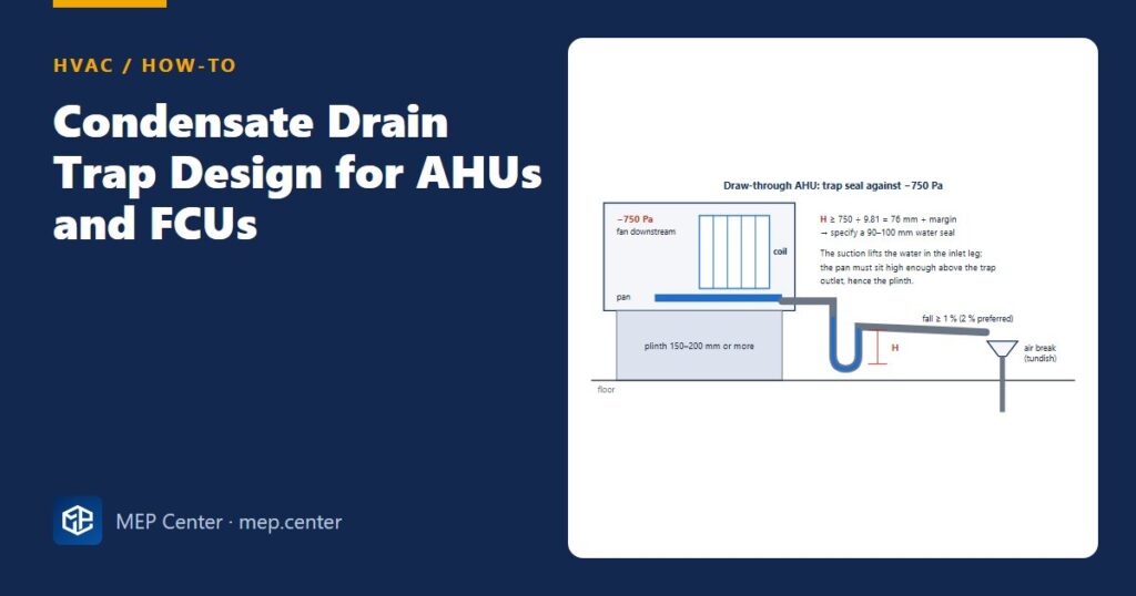
In a draw-through unit the fan sits after the coil, so the drain pan is below atmospheric pressure. Without a trap, or with a trap that is too shallow, air is sucked up the drain, water cannot leave the pan and it overflows into the unit. In a blow-through unit the pan is under positive pressure; without a trap, conditioned air blows out of the drain, often carrying water with it. Both need a trap, made to the manufacturer’s detail for that pressure.
How to design it, step by step
- Find the pressure at the drain pan from the fan selection, with dirty filters. Why: suction grows as the filters load, and the trap must still hold at the end of the filter life.
- Convert it to mm of water: Pa ÷ 9.81. Why: the water seal resists the pressure difference by its height alone (750 Pa ÷ 9.81 = 76 mm).
- Add a margin and set the seal height: −750 Pa → 90–100 mm; −250 to −300 Pa → 40–50 mm. Why: pressure swings at fan start-up can pull a seal that is only just deep enough.
- Check the height available under the pan connection. Why: a deep trap plus its outlet leg needs room; it is a common reason for 150–200 mm (or taller) AHU plinths. Fix the plinth height before the slab is cast.
- One trap per unit, connected directly at the drain outlet, and never two traps in series. Why: units at different pressures sharing one trap blow or suck through each other, and a double trap creates an air lock.
- Run the drain at ≥ 1 % fall (2 % preferred), not smaller than the unit connection, with a cleanout or open tee near the trap. Why: condensate carries dirt and biological slime; flat drains block.
- Discharge through an air break (tundish or open gully) into the building drainage. Why: foul air cannot be drawn back into the unit, and a blockage becomes visible.
- Insulate the drain in ceiling voids and heat-trace it outdoors. Why: cold condensate makes the pipe sweat, and outdoor traps freeze.
- Plan for dry traps: in winter, with no cooling, seals evaporate. Why: a dry trap leaks air; add a priming arrangement or use a listed self-sealing (ball or valve) trap.
How much water?
Condensate (kg/h) = latent load (kW) × 3600 / 2450, with 2450 kJ/kg the latent heat released per kg of water condensed. For an AHU you can also use ṁair × (Won − Woff).
Example: a cassette removing 0.6 kW of latent heat: 0.6 × 3600 / 2450 = 0.88 L/h. A fan coil with 0.25–0.5 kW latent makes about 0.4–0.7 L/h at peak.
A 2.0 m³/s outdoor air AHU (2.40 kg/s) drying air from 14.0 to 8.62 g/kg: 2.40 × 5.38 = 12.9 g/s = 46.5 kg/h, over a litre per minute on a design day. Its drain main is no longer a “small pipe” item.
| Pressure at drain pan | Seal height to specify | Typical unit |
|---|---|---|
| Small negative (FCU, cassette) | Manufacturer detail | Fan coils, cassettes with pumps |
| −250 to −300 Pa | 40–50 mm | Ducted indoor units, small AHUs |
| −750 Pa | 90–100 mm | AHUs with heat recovery and filters upstream |
| Positive (blow-through) | Manufacturer detail for positive pressure | Blow-through AHUs |
Condensate pumps
Where a gravity route is impossible, a condensate pump lifts the water to a high-level drain (cassettes often have built-in lifts of about 500–850 mm). Check the lift against the real route and wire the pump’s high-level alarm to stop the unit’s cooling, not just to raise an alarm. A failed pump without that interlock is a classic cause of ceiling water damage.
The trap height is part of the AHU selection; see AHU sizing quick rules and the processes behind the condensate in psychrometric chart AHU processes.
Typical values — verify with the edition adopted locally and with the unit manufacturer’s trap detail.
HVAC Systems Design — Heating, Cooling & Ventilation
28 modules from heat loss to plant room: boilers, heat pumps, cooling loads, psychrometrics, AHUs and ductwork. The VRF course is included.
Modules 1–3 are free, no account needed · full course €15,00 one-time
FAQ
How deep should an AHU condensate trap be?
Deeper than the drain pan suction in mm of water plus a margin. Divide the pressure in Pa by 9.81: at −750 Pa that is 76 mm, so specify a 90–100 mm seal.
Can two fan coils share one condensate trap?
No. Give every unit its own trap at its drain outlet. Units at different pressures sharing one trap can blow or suck air through each other, and the pans overflow.
What slope does a condensate drain need?
At least 1 %, with 2 % preferred, all the way to an air break or tundish connected to the drainage system.