
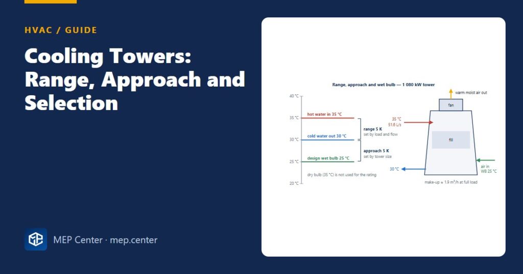
Cooling tower data sheets are written in three temperatures — range, approach and wet bulb — and a fourth number, the heat to reject, that is often taken wrongly from the chiller’s cooling capacity. Get these four right and the tower selection, the condenser water flow and the water consumption follow in a few lines.
The three temperatures
- Range = heat / (flow × cp). A 5 K range is the classic comfort value (35/30 °C); larger ranges reduce pumping and pipe sizes.
- Approach drives cost: halving it roughly doubles the tower. Typical design 4–6 K; below about 3 K is uneconomic.
- Wet bulb comes from the cooling-tower (evaporation) design data set for the site, not the dry-bulb data set or its coincident wet bulb. Add 0.5–1 K where towers sit in roof wells and may recirculate their own discharge.
Sizing in five lines
Heat rejection: 920 × (1 + 1/6) = 1 073 kW, plus a little pump heat → 1 080 kW.
Condenser water: 1 080 / (4.19 × 5) = 51.6 L/s (≈ 186 m³/h, 818 gpm).
Duty: 35 → 30 °C at 25 °C wet bulb, approach 5 K; 2 cells × 540 kW (25.8 L/s each) to match the two chillers.
Fan power: ≈ 0.01–0.02 kW per kW rejected → 11–22 kW total.
Sanity check: 1 080 kW / 4.4 kW per tower ton ≈ 246 tower tons; condenser flow ≈ 3 gpm per chiller ton (920 kW ≈ 262 TR → ≈ 785 gpm, close to the 818 gpm above because the load also includes compressor heat).
Water consumption
| Loss | Rule | 1 080 kW example |
|---|---|---|
| Evaporation E | ≈ 0.15 % of flow per K of range (≈ 0.85 × Q / 2 400 kJ/kg) | ≈ 1.4 m³/h |
| Drift D | 0.001–0.005 % of flow (modern ≤ 0.002 %) | ≈ 0.004 m³/h |
| Blowdown B | E / (C − 1) − D, cycles C typically 3–6 | ≈ 0.46 m³/h at C = 4 |
| Make-up M | E + D + B | ≈ 1.87 m³/h ≈ 1.7 m³/MWh |
Raising the cycles of concentration from 3 to 6 cuts blowdown from 0.70 to 0.28 m³/h — the business case for proper water treatment. Over about 1 200 equivalent full-load hours a year the example uses roughly 2 200 m³.
Selection and siting checklist
- Ask for independently certified thermal performance, fan power, sound power, operating weight, basin volume, drift rate and materials.
- For absorption chillers, rejection is far higher: Q × (1 + 1/COP) = 2.43 × Q at COP 0.7.
- Keep discharge above surrounding walls; respect clearances to walls and between cells; never put outdoor-air intakes downwind.
- Pumps below basin level with short suction lines; an equalising line between cells.
- No dead legs; plan a Legionella risk assessment, dosing, conductivity-controlled blowdown and regular cleaning and disinfection (at least once or twice a year).
- In cold climates, a winter strategy: basin heaters, drain-down or indoor sump, fan control.
- Use the colder water when the weather allows — condenser water reset rather than holding 30 °C all year.
The tower serves the plant described in chilled water pump head estimate; loads start from cooling load calculation basics, and the air side of the psychrometrics is in the psychrometric chart guide. Start-up checks are in the HVAC commissioning checklist.
Typical values — verify with the edition adopted locally and with certified manufacturer data.
HVAC Systems Design — Heating, Cooling & Ventilation
28 modules from heat loss to plant room: boilers, heat pumps, cooling loads, psychrometrics, AHUs and ductwork. The VRF course is included.
Modules 1–3 are free, no account needed · full course €15,00 one-time
FAQ
What is the difference between range and approach in a cooling tower?
Range is the hot water temperature in minus the cold water temperature out and depends on the heat load and the water flow. Approach is the cold water temperature minus the entering air wet bulb and depends on the tower’s size.
What approach should I design a cooling tower for?
Comfort cooling plants typically use 4–6 K. Approaches below about 3 K need a much larger tower and are rarely economic.
How much heat does a cooling tower reject?
The chiller’s cooling capacity plus its compressor energy, Q × (1 + 1/COP). A 920 kW chiller plant at COP 6 rejects about 1 080 kW; an absorption chiller at COP 0.7 rejects about 2.4 times its cooling capacity.