
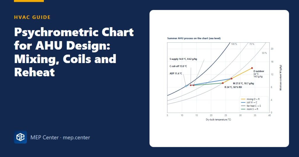
The psychrometric chart is the quickest way to check whether an air handling unit will really hold the room at 24 °C and 50 % RH. Every AHU section – mixing box, coil, fan, heater, humidifier, heat recovery – moves the air from one point on the chart to another. Draw those moves and you can size coils, predict condensate and spot impossible specifications before they reach the contractor.
- Any two independent properties fix a point on the chart; the other five can be read from it.
- Work with dry-air mass flow: Q = ṁ × Δh and condensate = ṁ × ΔW. Volume changes with temperature, mass does not.
- Supply airflow comes from the room sensible load; the supply moisture comes from the latent load. The supply point must sit on the room’s SHR line.
- Mixed air lies on the straight line between outdoor and return air, closer to the larger stream.
- A cooling coil line points at the apparatus dew point (ADP); the bypass factor tells you how many rows you need.
- Best single check: room load + outdoor air load + fan heat = coil load.
Reading the chart – seven properties
| Property | Unit | Where on the chart |
|---|---|---|
| Dry-bulb temperature t | °C | Horizontal axis, vertical lines |
| Moisture content W | g/kg dry air | Vertical axis, horizontal lines |
| Relative humidity φ | % | Curved lines; 100 % is the saturation curve |
| Wet-bulb temperature | °C | Diagonals meeting the saturation curve |
| Specific enthalpy h | kJ/kg dry air | Oblique scale, near the wet-bulb lines |
| Dew point | °C | Go horizontally left to the saturation curve |
| Specific volume v | m³/kg dry air | Steep diagonal lines |
Example: 24 °C / 50 % RH reads W = 9.3 g/kg, h = 47.8 kJ/kg, wet bulb ≈ 17.0 °C, dew point ≈ 12.9 °C, v ≈ 0.854 m³/kg. A coil surface below 12.9 °C condenses water from that air.
The two equations behind the chart, for sea level:
W = 0.622 × pw / (p − pw) h = 1.006 t + W × (2501 + 1.86 t)
pw = water vapour partial pressure, p = atmospheric pressure (101.325 kPa at sea level, about 84.6 kPa at 1500 m – use the site pressure), both in kPa; t in °C; W in kg/kg; h in kJ/kg. Never convert absolute enthalpies between SI and IP charts; their zero points differ.
Design values and coil data in this guide are typical – verify with the edition adopted locally and with manufacturer data.
Quick formulas for sensible, latent and total heat
| Quantity | SI (q in m³/s) |
|---|---|
| Sensible | Qs (kW) = 1.2 × q × Δt (K) |
| Latent | Ql (kW) = 3.0 × q × ΔW (g/kg) |
| Total | Qt (kW) = 1.2 × q × Δh (kJ/kg) |
These assume standard air (1.2 kg/m³). For coil balances use ṁ in kg/s and cp = 1.006 + 1.86 W (about 1.02 kJ/kg·K), as in the worked example.
The room condition line (SHR)
SHR = Qs / (Qs + Ql). Offices sit around 0.80–0.95, dense meeting rooms and auditoria 0.60–0.75, restaurants 0.65–0.80, server rooms close to 1.0.
Draw a line through the room point with the SHR slope. Any supply state on it, at the right mass flow, absorbs the room’s sensible and latent load in the right proportion. The flow follows from the sensible load and the supply temperature difference, typically 8–12 K:
ṁ = Qs / (cp × (troom − tsupply))
A supply point off the line lets room humidity drift. Room loads are explained in our cooling load calculation basics.
Mixing two air streams
Outdoor and return air mix along the straight line joining them, and the mixed point sits closer to the larger stream (the lever rule):
Wmix = (ṁ1W1 + ṁ2W2) / (ṁ1 + ṁ2), and the same for h. Dry-bulb mixes almost linearly too.
In winter, very cold outdoor air mixed with warm humid return air (pools) can cross the saturation curve – fog that wets filters and freezes on coils. Preheat the outdoor air first.
Cooling and dehumidifying – ADP and bypass factor
A coil whose surface is below the entering air’s dew point cools and dries at the same time. Its process line runs from the coil-on point towards the apparatus dew point (ADP) on the saturation curve – the effective coil surface temperature. In the classic model part of the air “bypasses” the fins:
BF = (toff − ADP) / (ton − ADP)
Typical bypass factors: 4-row 0.15–0.25, 6-row 0.08–0.15, 8-row 0.03–0.08; lower BF means more rows and more pressure drop. Select cooling coils at 2.0–2.5 m/s face velocity to avoid water carry-over.
Use this model to check selections: if the line through the coil-on and requested coil-off points never reaches the saturation curve, or reaches it colder than the chilled water allows, the specification is impossible.
Worked example – summer, recirculating AHU
Inputs
- Room R: 24 °C, 50 % RH → W 9.30 g/kg, h 47.8 kJ/kg
- Room loads: 24.0 kW sensible, 4.0 kW latent → SHR = 24 / 28 = 0.857
- Outdoor O: 34 °C, W 14.0 g/kg → h 70.1 kJ/kg
- Supply 14 °C (ΔT 10 K), draw-through fan heat 1.0 K, minimum outdoor air 0.70 kg/s, chilled water 6/12 °C
Step 1 – Supply mass flow from the sensible load
cp = 1.006 + 1.86 × 0.0093 = 1.023 kJ/kg·K; ṁ = 24.0 / (1.023 × 10) = 2.35 kg/s (≈ 1.95 m³/s). Return air = 2.35 − 0.70 = 1.65 kg/s.
Step 2 – Supply moisture from the latent load
ΔW = 4.0 / (2.35 × 2501) = 0.00068 kg/kg = 0.68 g/kg → WS = 9.30 − 0.68 = 8.62 g/kg. Supply S: 14.0 °C, 8.62 g/kg, h 35.9 kJ/kg. Check: 2.35 × (47.8 − 35.9) = 28.0 kW = 24 + 4 ✓.
Step 3 – Mixed air M
WM = (0.70 × 14.0 + 1.65 × 9.30) / 2.35 = 10.70 g/kg; hM = (0.70 × 70.1 + 1.65 × 47.8) / 2.35 = 54.4 kJ/kg; tM ≈ (0.70 × 34 + 1.65 × 24) / 2.35 = 27.0 °C.
Step 4 – Coil-off point C
The fan adds 1.0 K after the coil, so C = 14.0 − 1.0 = 13.0 °C at 8.62 g/kg, h 34.8 kJ/kg (about 92 % RH).
Step 5 – Coil duty and condensate
Qcoil = 2.35 × (54.4 − 34.8) = 46.1 kW (13.1 TR). Condensate = 2.35 × (10.70 − 8.62) / 1000 = 0.00489 kg/s = 17.6 kg/h – give this to the drainage designer. Latent part ≈ 2.35 × 0.00208 × 2501 = 12.2 kW, so the coil SHR ≈ 33.9 / 46.1 = 0.74, lower than the room’s 0.857 because the coil also dries the outdoor air.
Step 6 – ADP and bypass factor
Extending M → C to the saturation curve gives ADP ≈ 11.4 °C (8.39 g/kg). BF = (13.0 − 11.4) / (27.0 − 11.4) = 0.10 → a 6-row class of coil, easily achieved with 6/12 °C water. Chilled water flow = 46.1 / (4.19 × 6) = 1.83 kg/s (≈ 6.6 m³/h).
Sanity check
Room 28.0 kW + outdoor air 0.70 × (70.1 − 47.8) = 15.6 kW + fan heat 1.0 × 2.35 × 1.023 = 2.4 kW → 46.0 kW, matching the 46.1 kW found by enthalpy ✓. The fan heat is also consistent with 1.95 m³/s at about 800 Pa and 65 % overall efficiency (1.95 × 800 / 0.65 ≈ 2.4 kW).
Reheat and fan heat
When the room SHR is low (many people), the supply point may be warmer and drier than the coil delivers, so the air is overcooled and reheated. That costs twice: in the example above, 3 K of reheat means 2.35 × 1.023 × 3 = 7.2 kW of heating plus 7.2 kW of extra cooling. Prefer dry air from a dedicated outdoor air system or recovered heat over new energy.
Fan heat is a free reheat in draw-through units: roughly 1 K per 800 Pa with the motor in the airstream at 65 % efficiency. Leave it out and the supply is 1–2 K too warm.
Heating and humidification
Heating moves the point horizontally right: W stays, RH falls. Air at −5 °C / 80 % RH (2.0 g/kg) heated to 20 °C ends up at about 14 % RH. Two ways to add moisture:
- Steam: an almost vertical line. About 2.6 MJ per kg of steam, usually electric; needs an absorption distance and a high-limit humidistat downstream.
- Adiabatic (wetted media, nozzles): follows a constant wet-bulb line – W rises, temperature falls – so preheat first. Little electricity, but strict water hygiene.
Winter example: 1.20 kg/s of outdoor air through a 75 % plate heat exchanger goes from −5 °C to 15.25 °C (24.5 kW recovered). Reaching 20 °C and 5.0 g/kg then takes 5.8 kW of heating plus 9.5 kW of steam – or a 14.8 kW preheat to 27.5 °C and an adiabatic humidifier. Evaporating water costs the same energy either way; only the carrier and the maintenance change. Without heat recovery the heater alone would need 30.3 kW. How ventilation relates to room heat loss is covered in our heat loss calculation guide.
Heat recovery on the chart
Plates, run-around coils and heat pipes draw horizontal lines; enthalpy wheels draw diagonals because they also move moisture. With outdoor air at 34 °C / 14.0 g/kg, extract at 25 °C / 9.3 g/kg and 75 % efficiency, a plate cuts the outdoor air enthalpy by 7.0 kJ/kg, an enthalpy wheel by 16.0 kJ/kg – more than twice as much in humid climates.
Part-load humidity – the trap
On a mild, humid day a constant-volume unit controlled by room temperature runs the coil warmer, removes less moisture, and the room drifts to 60–70 % RH. Remedies: VAV, a dedicated outdoor air system at a fixed dew point, a humidity override with recovered reheat, and not oversizing the coil. Once the airflow is fixed, size the ductwork with our duct sizing guide.
Common mistakes
- Mixing volume flows instead of mass flows, or ignoring density at altitude.
- Coil-off state off the room condition line – room humidity drifts.
- Forgetting fan heat in draw-through units.
- Specifying a coil-off condition that needs an ADP colder than the chilled water allows.
- Forgetting the outdoor air latent load – undersized coils in humid climates.
- Adiabatic humidifier without preheat; steam humidifier without a high-limit humidistat.
Quick checklist
- Indoor and outdoor design states fixed, with site pressure, and plotted.
- Room sensible and latent loads and SHR known for each zone.
- Supply state on the room line; supply mass flow from the sensible load.
- Mixed point from a mass balance; coil ADP and bypass factor realistic; duty checked as room + outdoor air + fan.
- Condensate flow passed to the drainage designer.
- Winter: heat recovery leaving state, frost risk, heater and humidifier energy.
- State point table on the AHU schematic.
HVAC Systems Design — Heating, Cooling & Ventilation
28 modules from heat loss to plant room: boilers, heat pumps, cooling loads, psychrometrics, AHUs and ductwork. The VRF course is included.
Modules 1–3 are free, no account needed · full course €15,00 one-time
FAQ
How do I find the dew point on a psychrometric chart?
From the state point, move horizontally (constant moisture content) to the left until you meet the saturation curve and read the temperature there. For 24 °C and 50 % RH that is about 12.9 °C.
What is the apparatus dew point of a cooling coil?
It is the effective coil surface temperature: the point where the coil process line, extended, meets the saturation curve. In the worked example the line from 27.0 °C to 13.0 °C reaches saturation at about 11.4 °C.
What is a typical bypass factor?
About 0.15–0.25 for a 4-row coil, 0.08–0.15 for 6 rows and 0.03–0.08 for 8 rows, depending on fin spacing and face velocity. A lower bypass factor needs more rows and more air pressure drop.
Why is the coil load larger than the room load?
The coil also cools and dries the outdoor air and absorbs the fan heat. In the worked example the room needs 28.0 kW but the coil 46.1 kW, because outdoor air adds 15.6 kW and the fan 2.4 kW.
Steam or adiabatic humidification – which uses less energy?
The total energy is almost the same, because evaporating water costs the same either way. Steam usually uses electricity; adiabatic humidifiers take the energy from a preheating coil and need strict water hygiene.