
Every radiator, underfloor circuit, pipe, pump and boiler you select rests on one number per room: the design heat load. Too low and rooms are cold on the coldest morning; too high – the more common mistake – and you buy oversized plant that cycles and wastes energy. This guide walks you through a heat loss calculation step by step, the EN 12831 way, with one room calculated completely.
- Design heat load = transmission loss + ventilation loss (+ reheat only if intermittent heating is really designed). Internal gains are never subtracted.
- Each loss is a heat transfer coefficient H (W/K) multiplied by the indoor–outdoor temperature difference.
- Use the whole-window Uw, count thermal bridges once, and use reduction factors for the ground and unheated spaces.
- Ventilation: take the larger of infiltration and the minimum hygienic air flow, never the sum. HV = 0.33 × V̇ (m³/h).
- Size emitters on room loads and the heat source on the building load, which is smaller than the sum of rooms.
- Sanity check: a corner living room in a moderately insulated house at −10 °C lands around 40–60 W/m².
What the design heat load actually is
The design heat load is the heat you must supply to hold a room at its design indoor temperature while the outdoor air sits at its design value. EN 12831 writes it for each heated room as:
ΦHL = ΦT + ΦV (+ ΦRH)
- ΦT – transmission through walls, windows, roof and floor, including thermal bridges (W)
- ΦV – ventilation: heating the air that leaks or is brought in (W)
- ΦRH – reheat after a setback, only for designed intermittent heating (W)
Both main terms take the form Φ = H × (θint − θe), with H a heat transfer coefficient in W/K: find the H values, then multiply by the design temperature difference. People, lights and sun are left out – the design case is a cold, overcast morning in an empty building. ASHRAE uses the same physics in IP units.
Step 1 – Fix the design conditions
Typical winter indoor design temperatures: 20 °C for living rooms and bedrooms, 20–21 °C for offices, 24 °C for bathrooms, 15–18 °C for corridors and stairs, 12–16 °C for warehouses. The outdoor design temperature θe comes from the national annex of EN 12831; in ASHRAE practice you use the 99.6 % heating dry bulb (exceeded about 35 hours a year) or the 99 % value (about 88 hours). For ground losses you also need the annual mean outdoor temperature θm,e.
The values in this guide are typical – verify with the edition and national annex adopted locally.
Step 2 – Calculate U-values from the real build-up
For a layered wall, add the resistances and invert:
Rtotal = Rsi + Σ(d / λ) + Rse → U = 1 / Rtotal
d is the layer thickness in m, λ its thermal conductivity in W/mK. Surface resistances: Rsi = 0.13 m²K/W for walls, 0.10 for roofs (heat flow up), 0.17 for floors (heat flow down); Rse = 0.04 m²K/W.
Example: 15 mm plaster (R 0.026) + 190 mm perforated clay block (0.576) + 80 mm insulation at λ 0.035 (2.286) + 10 mm render (0.011) + surface resistances (0.17) gives Rtotal = 3.069 m²K/W, so U = 0.326 ≈ 0.33 W/m²K. The insulation alone provides about 75 % of the resistance.
For windows, use the manufacturer’s whole-window Uw: a centre-of-glass Ug of 1.0 can mean Uw = 1.3 W/m²K.
Step 3 – Measure areas and add thermal bridges once
Net wall area = gross wall minus openings; window area = structural opening. Floors and ceilings between rooms at the same temperature give no loss. Keep one dimension convention: EN 12831 normally uses external dimensions, some national methods internal ones.
Thermal bridges (balcony slabs, slab edges, window reveals) are handled in one of two ways – never both:
- Simplified: add ΔUTB to every envelope U-value – about 0.02–0.05 W/m²K for careful details, 0.10 W/m²K as a common default, around 0.15 for poor details.
- Detailed: HTB = Σ ψ × l. A 5 m continuous concrete balcony slab at ψ = 0.7 W/mK adds 3.5 W/K, or 105 W at a 30 K difference. A thermal-break element (ψ around 0.10–0.25) removes most of that.
Step 4 – Unheated spaces and the ground
A wall to an unheated garage or stair does not see the full outdoor ΔT. EN 12831 uses a reduction factor:
bu = (θint − θu) / (θint − θe)
θu is the unheated space’s estimated temperature: a +5 °C garage, 20 °C inside, −10 °C outside gives bu = 15 / 30 = 0.50. National defaults are roughly 0.4–0.9.
The ground sits near the annual mean temperature. The simplified method writes Hg = fg1 × fg2 × A × Uequiv × Gw, with fg1 = 1.45, fg2 = (θint − θm,e) / (θint − θe), Uequiv read from the standard’s tables for the floor’s characteristic dimension B’ = A / (0.5 × P), and Gw = 1.0 (or 1.15 when groundwater is within 1 m). Calculating a slab at full outdoor ΔT overstates its loss two to four times.
Step 5 – Ventilation loss
HV = 0.33 × V̇ (W/K, with V̇ in m³/h; 0.33 = 1.2 kJ/m³K ÷ 3.6)
For a naturally ventilated room, V̇ is the larger of two flows:
- Infiltration: V̇inf = 2 × V × n50 × e × ε, where V is the room volume (m³), n50 the blower-door air change rate at 50 Pa (h⁻¹), e the shielding coefficient (for example 0.03 for moderate shielding with openings on more than one façade) and ε the height correction (1.0 up to 10 m).
- Minimum hygienic flow: V̇min = nmin × V; typical nmin: living rooms and bedrooms 0.5 h⁻¹, kitchens and bathrooms 1.5, offices 1.0, meeting rooms and classrooms 2.0.
With heat recovery, the supply arrives at θsu = θe + η × (θint − θe): at η = 0.80, −10 °C outside and 20 °C inside that is 14 °C, and the room loss falls to 20 %. If the AHU reheats the air to room temperature, the load has moved to the AHU coil – see our psychrometric chart and AHU process guide.
Worked example – one living room, start to finish
Inputs
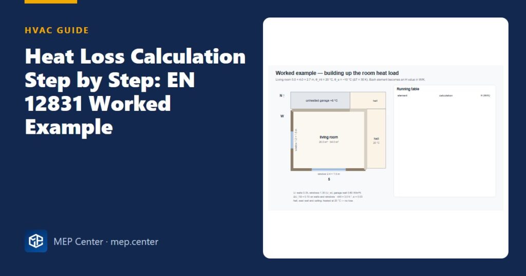
- Corner living room, ground floor, internal size 5.0 × 4.0 m, clear height 2.7 m → floor 20.0 m², volume 54.0 m³
- θint = 20 °C, θe = −10 °C (ΔT = 30 K), θm,e = 10 °C
- External walls: gross 13.5 + 10.8 = 24.3 m², windows 3.6 + 1.8 = 5.4 m², net wall 18.9 m², U = 0.35 W/m²K (a slightly less insulated wall than the section above)
- Windows Uw = 1.30 W/m²K; thermal bridges by ΔUTB = 0.10 W/m²K on walls and windows
- Wall to garage 4.0 × 2.7 = 10.8 m², U = 0.60, bu = 0.50
- Slab on ground 20.0 m², Uequiv = 0.20 (B’ = 6 m), Gw = 1.0
- n50 = 3.0 h⁻¹, e = 0.03, ε = 1.0; nmin = 0.5 h⁻¹; continuous heating, no reheat
Transmission
- External walls: 18.9 × (0.35 + 0.10) = 18.9 × 0.45 = 8.505 W/K
- Windows: 5.4 × (1.30 + 0.10) = 5.4 × 1.40 = 7.560 W/K
- Wall to garage: 10.8 × 0.60 × 0.50 = 3.240 W/K
- Ground floor: fg2 = (20 − 10) / (20 + 10) = 0.333; Hg = 1.45 × 0.333 × 20.0 × 0.20 × 1.0 = 1.933 W/K
- HT = 8.505 + 7.560 + 3.240 + 1.933 = 21.238 W/K → ΦT = 21.238 × 30 = 637 W
Ventilation
- Infiltration: 2 × 54.0 × 3.0 × 0.03 × 1.0 = 9.72 m³/h
- Minimum: 0.5 × 54.0 = 27.0 m³/h → the minimum governs, V̇ = 27.0 m³/h
- HV = 0.33 × 27.0 = 8.91 W/K → ΦV = 8.91 × 30 = 267 W
Result
ΦHL = 637 + 267 = 904 W ≈ 0.90 kW (about 3 080 Btu/h), or 904 / 20.0 = 45.2 W/m².
Sanity check
45 W/m² sits inside the expected 40–60 W/m² band. Cross-check: total H = 21.238 + 8.91 = 30.15 W/K, and 30.15 × 30 = 904 W ✓.
From rooms to the whole building
The heat source is not sized on the sum of the room loads, for three reasons:
- Internal transfers cancel – a 24 °C bathroom’s loss into a 20 °C bedroom is that bedroom’s gain.
- Wind blows from one side at a time – only part of the summed infiltration counts (a factor of 0.5 in the classic 2003 method).
- Reheat, if designed, is added once for the building.
For the house our living room belongs to, nine rooms sum to 4 484 W; cancelling internal transfers (−80 W) and infiltration diversity (−120 W) give a building load of about 4 280 W ≈ 4.3 kW. Emitters are sized on room loads; the heat source on 4.3 kW plus any hot water demand that cannot run on priority – not 4.5 kW plus 20 % “just in case”. Once you have flows, the next step is the pipework: see our hydronic heating pipe sizing guide.
Reheat allowance – only when you mean it
If a school or office cools down overnight, EN 12831 adds ΦRH = A × fRH, typically 5–30 W/m². Well-insulated buildings barely cool, and heat pumps prefer continuous operation, so it is often zero. Never stack reheat, a safety margin and rounded-up U-values.
On the drawings
Tag every room with its temperature and load, for example “G.03 Living / 20 °C / 0.90 kW”, and explain in the report why the building load differs from the sum of rooms. Summer works very differently – see our cooling load calculation basics.
Common mistakes
- Using the centre-of-glass Ug instead of the whole-window Uw.
- Ignoring thermal bridges, or counting them twice (ψ values and a ΔU surcharge).
- Calculating the ground floor at full outdoor ΔT instead of with the ground method.
- Adding infiltration and minimum ventilation together instead of taking the larger.
- Subtracting internal gains.
- Stacking margins, or sizing the heat source on the plain sum of room loads.
Quick checklist
- Standard, national annex, θe, θm,e and room temperatures recorded with their source; one dimension convention.
- U-values calculated from real build-ups; windows with Uw.
- Thermal bridges counted once; ground floors with the ground method; unheated spaces with bu.
- V̇ = max(infiltration, minimum); mechanical supply at its temperature after heat recovery.
- Reheat only if intermittent operation is really designed.
- W/m² plausibility check on every room; building load with diversity explained.
HVAC Systems Design — Heating, Cooling & Ventilation
28 modules from heat loss to plant room: boilers, heat pumps, cooling loads, psychrometrics, AHUs and ductwork. The VRF course is included.
Modules 1–3 are free, no account needed · full course €15,00 one-time
FAQ
What is the difference between room heat load and building heat load?
The room heat load sizes the emitter in that room. The building heat load sizes the boiler or heat pump and is smaller, because heat transfers between rooms cancel and wind-driven infiltration does not hit every façade at once.
Should I subtract internal gains from people and lighting?
No. The design case is a cold, overcast morning with the building unoccupied, so internal gains are a bonus in operation, not a design input.
Which outdoor design temperature should I use?
Use the value from the national annex of EN 12831 for your location. In ASHRAE practice use the 99.6 % or 99 % heating dry bulb from the climatic data, and record the source in the design basis.
What heat loss in W/m² is normal?
For a corner living room in a moderately insulated house at −10 °C, around 40–60 W/m² is plausible. Around 100 W/m² usually means an input error or a very old building, and around 20 W/m² a near-passive building.
Should I add a safety margin to the heat loss?
Avoid stacking margins. Design conditions already carry a statistical margin, so if you add anything, add one stated allowance and do not also round up U-values or add reheat without intermittent operation.