
A fire pump adds pressure to a supply that already has enough water but not enough pressure at the required flow. Get the sizing wrong and you either starve the sprinklers or end up with a pump that spends its life near shut-off, over-pressurising every fitting in the building. This guide shows you how to size a fire pump to NFPA 20 in clear steps, with a fully worked tank-fed example.
- Choose the rated flow at or just above the demand flow from the standard list (for example 2839 L/min / 750 gpm). Oversizing is not “safe”.
- Net pressure = discharge − suction. Take the suction at the worst source condition: the lowest usable tank level or the lowest city residual.
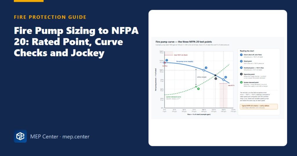
- The certified curve must pass three NFPA 20 points: churn ≤ 140 %, rated ≥ 100 %, and ≥ 65 % pressure at 150 % flow.
- Check churn + maximum static suction against the component rating, typically 12.1 bar (175 psi).
- Size the motor for the peak power up to 150 % flow, not for the rated point.
- The jockey pump must be smaller than one sprinkler’s flow, and its settings must step down: stop → −0.7 bar (10 psi) → −0.35 bar (5 psi).
When you need a fire pump
A pump does not create water. On a weak city main or an undersized tank it fails just as surely as no pump at all. You normally need one when:
- the city supply curve lies below the demand point plus margin, and bigger pipes cannot close the gap economically;
- the water comes from a suction tank, reservoir or other unpressurised source;
- standpipes need residual pressures at the top outlets that no main can give, which is typical in tall buildings;
- special systems such as ESFR, foam-water or water spray have high pressure demands.
The demand point itself comes from the hydraulic calculation. If you have not done it yet, follow our step-by-step sprinkler hydraulic calculation first. The flow it produces depends heavily on the hazard class, as explained in our sprinkler hazard classification guide.
What you need before you select a pump
| Input | Where it comes from |
|---|---|
| System demand: flow and pressure at the pump discharge flange | Hydraulic calculation, transferred from the base of riser to the pump |
| Suction pressure: minimum and maximum static, residual at flow | City flow test, or the lowest and full tank levels |
| Maximum allowable system pressure | Component ratings, typically 12.1 bar (175 psi) |
| Power reliability | Electrical engineer and utility |
| Room, access and fire separation | Architect and fire strategy |
Fire pumps are listed centrifugal pumps. Horizontal split-case pumps are the default for flooded suction. End-suction and vertical in-line pumps suit small, compact rooms. A vertical turbine pump is the only type allowed when the water level is below the pump (wet pits, wells, below-grade tanks), because horizontal fire pumps may not run with a suction lift.
Pump curve limits, pipe sizes and settings in this guide are typical NFPA 20 values in our own summary. Verify them with the edition adopted locally and with the certified pump data.
The three points every fire pump curve must pass
| Point | NFPA 20 requirement | Why it matters |
|---|---|---|
| Churn (0 % flow) | Net pressure ≤ 140 % of rated | Protects pipes and fittings at low flow, which is when the pump runs most |
| Rated (100 % flow) | Net pressure ≥ 100 % of rated | Delivers the design point |
| Overload (150 % flow) | Net pressure ≥ 65 % of rated | Gives a flat, robust curve when more heads or hoses open |
Listed pumps come with a certified shop test curve. Typical split-case pumps churn at about 110–125 % and deliver 70–80 % of rated pressure at 150 % flow, well inside the limits.
How to select the rated flow and pressure
- Move the demand to the pump discharge. Add friction and elevation between the pump and the base of riser, plus the losses of the discharge check and control valves.
- Find the suction pressure at the demand flow under the worst condition: the lowest usable tank level minus suction friction, or the lowest city residual.
- Net pressure required = demand at discharge − suction pressure.
- Rated flow ≥ demand flow, from the standard list (… 500, 750, 1000, 1250, 1500 … gpm).
- Rated pressure = required net pressure + your stated margin. Practice is 0.7 bar (10 psi) or 10 %, and it is not an NFPA value.
- Check the certified curve against the three points, and confirm the demand point lies below it.
- Check maximum pressure: churn + maximum static suction ≤ component rating.
Keep the demand at or just below the rated flow. A 1500 gpm pump on a 600 gpm demand runs near churn all its life, with high pressures, a larger driver, larger test equipment and a bigger room.
Maximum pressure and relief valves
The highest pressure in the system is churn net pressure + maximum static suction (full tank or highest city static). If it exceeds the typical 12.1 bar (175 psi) component rating, you can choose a flatter curve or a lower rated pressure, use higher-rated components (for example 20.7 bar / 300 psi), or use a listed variable speed pressure limiting control where it is permitted.
A main relief valve is required on a diesel pump where 121 % of net churn plus maximum static suction exceeds the component rating. The 121 % allows for 10 % engine overspeed, because pressure rises with speed squared (1.10² = 1.21). Never use a relief valve to hide an oversized electric pump. Every pump also needs a small circulation relief valve so that it does not overheat at churn. The exception is a diesel engine cooled by water taken from the pump discharge.
Electric motor or diesel engine
Pump power rises with flow, so the motor must not exceed its nameplate rating × service factor (commonly 1.15) at any flow up to 150 %. To estimate the power from the curve:
P (kW) = Q × p / (600 × η), where Q is in L/min, p is the net pressure in bar and η is the pump efficiency. In US units, BHP = Q × H / (3960 × η), with Q in gpm and H in ft of water (psi × 2.31).
Diesel engines are derated by about 3 % per 300 m (1000 ft) above 91 m (300 ft) of altitude, and by about 1 % per 5.6 °C (10 °F) above 25 °C (77 °F). The derated power must still exceed peak pump power. Choose a diesel where the utility is unreliable, or as the second pump alongside an electric one.
Suction piping rules reviewers check first
- Velocity ≤ 4.6 m/s (15 ft/s) at 150 % flow near the pump, and not smaller than the NFPA 20 table size (8″ for a 750 gpm pump).
- Suction pressure at the flange ≥ 0 at 150 % flow. About −0.2 bar (−3 psi) is allowed for a tank whose base is at or above the pump.
- No elbow in a plane parallel to the shaft within 10 pipe diameters of the suction flange.
- An eccentric reducer with the flat side on top, so that no air pocket can form. A concentric reducer is not acceptable.
- Only a listed OS&Y gate valve within 15 m (50 ft) of the flange. No butterfly valves there.
- Check valves and backflow preventers at least 10 diameters from the flange.
Jockey pump and pressure settings
The jockey pump makes up small leaks so that the main pump does not start for every drip. Size it to restore allowable leakage in about 10 minutes, typically around 1 % of the main pump flow. It must stay below one sprinkler’s flow (a K80 head at 0.5 bar gives about 56 L/min / 14.8 gpm), so that a single open sprinkler pulls the pressure down and starts the main pump.
| Setting | Typical rule (NFPA 20 annex logic) |
|---|---|
| Jockey stop | Main pump churn + minimum static suction |
| Jockey start | Jockey stop − 0.7 bar (10 psi) |
| Main pump start | Jockey start − 0.35 bar (5 psi) |
| Second pump start | Main pump start − 0.7 bar (10 psi) |
Every setting must stay above the system demand pressure. With a city main as suction, base the settings on the minimum city static, so that daily pressure swings do not start the main pump.
Worked example: 2839 L/min at 6.55 bar from a suction tank
Inputs. System demand at the pump discharge flange: 2839 L/min at 6.55 bar (750 gpm at 95 psi). Suction tank: lowest usable level 1.22 m (4 ft) above the pump centreline, full level 6.1 m (20 ft) above. Suction friction at demand: 0.03 bar (0.4 psi). Components rated 12.1 bar (175 psi). Electric drive, reliable utility.
- Suction at demand (worst case). 4 ft × 0.433 = 1.73 psi − 0.4 = +1.3 psi (0.09 bar).
- Net pressure required. 95 − 1.3 = 93.7 psi (6.46 bar) at 750 gpm.
- Rated point. 750 gpm is a standard size equal to the demand. A 100 psi pump would leave only 6.3 psi of margin, so select 750 gpm at 105 psi (2839 L/min at 7.24 bar). Discharge at demand ≥ 105 + 1.3 = 106.3 psi, a margin of 11.3 psi (0.78 bar) ✓.
- Curve check. Certified curve: churn 124 psi, 106 psi at 750 gpm, 80 psi at 1125 gpm. Churn limit 1.40 × 105 = 147 psi → 124 psi (118 %) ✓. Rated ≥ 105 psi → 106 psi ✓. At 150 %: ≥ 0.65 × 105 = 68.25 psi → 80 psi (76 %) ✓.
- Maximum pressure. 124 + 20 × 0.433 = 124 + 8.66 = 132.7 psi (9.15 bar) ≤ 175 psi ✓. Even a diesel would pass: 1.21 × 124 + 8.66 = 158.7 psi.
- Motor. At rated: 750 × (106 × 2.31) / (3960 × 0.73) = 63.5 hp (47.4 kW). At 150 %: 1125 × (80 × 2.31) / (3960 × 0.68) = 77.2 hp (57.6 kW). A 75 hp motor with a 1.15 service factor gives 86.3 hp ✓. In IEC sizes, a 55 kW motor × 1.15 = 63.3 kW ✓. Go one size up if the published curve peaks close to the limit.
- Pipes. 8″ suction: v = 0.4085 × 1125 / 7.981² = 7.2 ft/s (2.2 m/s) ≤ 15 ft/s ✓. Keep any elbow parallel to the shaft at least 10 × 8″ = 2.0 m (80 in) from the flange. 6″ discharge: 12.5 ft/s (3.8 m/s). Test header: 3 × 2½” (65 mm) hose valves on a 6″ header. Flow meter loop sized for ≥ 175 % = 4970 L/min (1313 gpm).
- Jockey. 1 % × 750 = 7.5 gpm → select about 30 L/min (8 gpm), below one sprinkler’s 14.8 gpm ✓. Stop = 124 + 1.7 = 126 psi (8.7 bar). Start = 116 psi (8.0 bar). Main pump start = 111 psi (7.65 bar). All are above the 95 psi demand ✓.
- Tank. Size it for the demand, not the pump: 750 gpm × 60 min = 45,000 gal = 170 m³ net, plus dead water and freeboard.
Sanity check. Margin on the curve: 106 − 93.7 = 12.3 psi (0.85 bar) net ✓. Churn ratio 124/105 = 1.18, inside the typical 110–125 % band ✓. Maximum pressure leaves 42 psi (2.9 bar) of headroom to the 175 psi rating, so no main relief valve is needed for an electric drive.
Testing provisions you must leave room for
Every fire pump is tested at churn, 100 % and 150 % flow, at acceptance and throughout its life. Provide a test header to outside, with 2½” (65 mm) hose valves sized for the 150 % flow and a place where that water can run away. Add a flow meter loop back to the tank, sized for at least 175 % of rated flow. A loop back to the suction proves the pump but not the supply. The acceptance test typically includes at least six automatic and six manual starts with at least one hour of total running.
Common mistakes
- Selecting on the rated point only, without checking churn + maximum suction against 12.1 bar (175 psi).
- Taking the suction pressure at full tank or at city static instead of the lowest usable level or residual.
- Oversizing the pump “for the future”, so that it runs near churn.
- Sizing the motor at the rated point and then overloading it at 150 % flow.
- Fitting a butterfly valve, a concentric reducer or a close-coupled elbow on the suction.
- Choosing a jockey pump larger than one sprinkler’s flow, so that one open head never starts the main pump.
- Setting jockey and main pump to start at the same pressure.
- Protecting the fire pump supply like an ordinary motor circuit, so that it trips during a long start.
Quick checklist
- Demand transferred to the pump discharge flange, with valve and pipe losses.
- Suction pressure at the worst source condition; maximum static noted separately.
- Rated flow from the standard list, at or just above the demand; margin stated.
- Certified curve checked at churn, 100 % and 150 %, with the demand below the curve.
- Churn + maximum suction ≤ component rating; relief valve need checked for diesel.
- Motor or engine sized on peak power up to 150 %, with derating for diesels.
- Suction size, velocity, valves, reducer and elbow distance checked.
- Jockey flow below one sprinkler; stop, start and main-start settings in a cascade.
- Test header, meter loop, drainage and room separation shown on the drawings.
Fire Protection & Suppression Systems Design (NFPA)
20 narrated modules with animated diagrams, two complete worked projects (DWG + DXF), the Fire Calc Workbook and an online calculator.
Modules 1–3 are free, no account needed · full course €15,00 one-time
FAQ
How do I choose the rated flow of a fire pump?
Pick the standard rating at or just above the system demand flow, for example 750 gpm (2839 L/min) for a 750 gpm demand. The curve allows the demand up to 150 % of rated, but most designers keep it at or below the rated flow.
What are the NFPA 20 pump curve limits?
Churn pressure must not exceed 140 % of rated pressure, the rated point must give at least 100 %, and at 150 % of rated flow the pump must still give at least 65 % of rated pressure.
Which suction pressure should I use for sizing?
Use the worst condition at the demand flow: the lowest usable tank level minus suction friction, or the lowest city residual pressure. Use the maximum static suction only to check the highest system pressure.
How big should the jockey pump be?
Typically about 1 % of the main pump flow, enough to make up leakage in about 10 minutes, and always less than one sprinkler’s flow so that an open sprinkler starts the main pump.
Do I always need a main relief valve?
No. It is required on diesel pumps where 121 % of churn plus maximum static suction exceeds the component rating, and on some variable speed arrangements. It must not be used to correct an oversized electric pump.
More Fire Protection (Sprinklers, NFPA) articles
- Sprinkler Hydraulic Calculation: A Step-by-Step Worked Example
- Fire Hydrant Connection to the Fire Main (NFPA 24 Practice)
- EN 12845 vs NFPA 13: Key Differences for Designers
- Kitchen Hood Wet Chemical Systems: Design Basics
- Dry Pipe vs Preaction: Choosing the Sprinkler System Type
- Sprinkler Obstruction Rules: A Quick Field Guide