
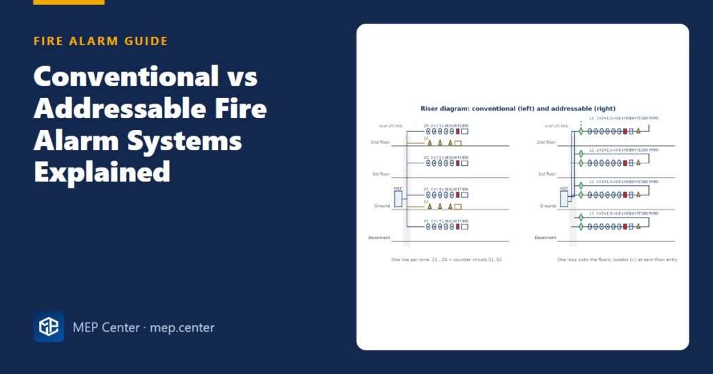
Conventional or addressable? It is usually the first decision on a fire alarm project, and getting it wrong is expensive either way: an addressable panel in a small shop is money wasted, while a conventional system in a multi-storey building with lifts, dampers and pressurisation turns every alarm into a floor-by-floor search. This guide explains how each system works, where each one fits, and the alarm-device rules that apply to both.
- Conventional: radial zone circuits, each supervised by an end-of-line resistor, typically up to 32 devices per zone. The panel knows the zone, not the device.
- Analogue addressable: a loop that returns to the panel, 127–250 addresses per loop; the panel names the exact device, and isolators keep the loop alive after a short.
- Rule of thumb: once zone count and search time become a problem – several storeys, search paths over 60 m, interfaces – go addressable.
- Both systems follow the same design rules (CEN/TS 54-14 or NFPA 72) and EN 54 product standards; only the wiring and the information differ.
- Alarm sound: at least 65 dB(A) or 10 dB(A) above ambient, 75 dB(A) at the bedhead in sleeping areas, never above 118 dB(A).
- Phased evacuation, crowds or tall buildings point to voice alarm instead of sounders.
What every fire alarm system does
Whatever the technology, the system has four blocks: it detects (detectors, manual call points), it warns (sounders, beacons, voice alarm), it triggers other systems (lifts, dampers, pressurisation, door holders, suppression), and in the middle sits the control and indicating equipment – the panel – with its power supply and batteries. Every design step belongs to one of these blocks, and every block is tested at handover.
How a conventional system works
The building is split into zones. Each zone is a two-wire radial circuit from the panel, wired in and out through every detector and call point – never in a star – and finished with an end-of-line (EOL) resistor at the last device. The resistor lets the panel supervise the line: an open circuit stops the current and shows a fault; a detector in alarm lowers the resistance and shows a fire. Sounders run on separate circuits, also supervised by an EOL.
- Typically up to 32 devices per zone.
- The panel display says “Fire – Zone 3”; someone must walk the zone to find the detector.
- Cheap devices, simple commissioning, but a cable to every zone.
- Interfaces need separate relays per zone – fine for one or two, awkward for a cause-and-effect matrix.
How an addressable system works
All devices sit on a loop that leaves the panel and returns to it. Every device has an address, so the panel shows “Loop 3, address 47: 2nd floor corridor smoke detector”. Analogue addressable detectors report a measured value, and the panel makes the alarm decision. Because the loop is fed from both ends, a single break loses nothing; short-circuit isolators limit a short to one section.
- 127–250 addresses per loop, depending on the manufacturer – designed to 80 % at most.
- Fault location at device level; maintenance can see dirty detectors before they false-alarm.
- Input/output modules on the loop handle dampers, lifts, sprinkler flow switches and door holders.
- Loop-powered base sounders and beacons cut the separate sounder wiring.
- Dearer devices, less cable, much easier operation in large buildings.
Zones still exist in an addressable system – as software groups with meaningful names – and the same zone rules apply. See our fire alarm loop design guide for the address budget and isolator rules.
Side-by-side comparison
| Conventional | Analogue addressable | |
|---|---|---|
| Wiring | Radial zone circuit with EOL resistor | Loop out and back to the panel |
| Devices | Typically up to 32 per zone | 127–250 per loop (design to 80 %) |
| Alarm information | Zone | Exact device and location text |
| Fault location | Zone level | Device level; isolators contain shorts |
| Interfaces | Few, via zone relays | Many, via loop modules and cause-and-effect programming |
| Best for | Small, low-rise buildings with a few zones | Medium and large, multi-storey, buildings with interfaces |
| Cost pattern | Cheap devices, more cable | Dearer devices, less cable, easier operation |
How to choose
The building code tells you which buildings need a system; CEN/TS 54-14 (or NFPA 72) tells you how to design it. Within that, the choice between conventional and addressable comes down to four questions:
Alarm devices: rules that apply to both systems
Sound levels
- At least 65 dB(A) everywhere the alarm must be heard, or 10 dB(A) above any ambient noise lasting more than 30 s – whichever is greater.
- 75 dB(A) at the bedhead where sleeping people must be woken.
- Never more than 118 dB(A) where people may be; tone in the 500–2000 Hz band; at least one sounder per fire compartment.
- Door losses: about 20 dB(A) for a normal door, 30 dB(A) for a fire door.
- Sounders and beacons at least 2.1 m above the floor.
Sound in free field falls by 20·log10(d) from the level at 1 m, where d is the distance in metres – about 6 dB per doubling of distance. That is why a few loud sounders rarely work: door losses and the 118 dB ceiling push you towards many small devices, and in addressable systems loop-powered base sounders keep the wiring simple.
Sound levels, device limits and the NFPA figures in this article follow our fire alarm course (CEN/TS 54-14, EN 54 and NFPA 72, 2022). They are typical — verify with the edition adopted locally and the authority having jurisdiction.
Visual alarms and voice alarm
Visual alarm devices (EN 54-23) are needed where hearing-impaired people may be present, where ambient noise exceeds about 90 dB(A) and where hearing protection is worn. Their coverage is declared as a class: W-2.4-6 is a wall device mounted at 2.4 m that covers a 6 × 6 m area at 0.4 lux. Flash rates of 0.5–2 Hz, synchronised. In bedrooms a beacon alone does not wake people – add a vibrating pillow pad.
Where evacuation is phased – high-rise buildings, malls, hospitals, stadiums – use voice alarm (EN 54-16 / 54-24) with intelligibility STI ≥ 0.5, supervised speaker lines and fire-resistant cabling.
Worked example: which system, and does the sound reach?
Inputs. 3-storey office, 1,500 m² per floor, one fire compartment per floor. Per floor: 45 smoke detectors and 4 call points. Lifts, stair pressurisation and smoke dampers must be controlled. Corridor sounders rated 100 dB(A) at 1 m.
Step 1 – conventional zoning. Area per floor 1,500 m² ≤ 2,000 m² ✓, but devices per floor = 45 + 4 = 49 > 32 → 2 zones per floor, so 6 zones. Each alarm shows only “Zone 4”: someone walks half a floor to find the detector. Every interface needs its own relay and wiring.
Step 2 – addressable budget. Per floor: 45 + 4 + 8 loop sounders + 2 modules = 59 addresses; building = 3 × 59 = 177. With 127-address loops: 177 ÷ (127 × 0.8) = 177 ÷ 101.6 = 1.74 → 2 loops. With 250-address loops one loop would carry 177 ÷ 250 = 71 % – within 80 %, but two loops split by floors limit the impact of cable damage.
Decision: three storeys plus lift, pressurisation and damper interfaces → analogue addressable.
Step 3 – sound check. End of corridor, 12 m from the sounder: 100 − 20·log10(12) = 100 − 21.6 = 78.4 dB(A) ≥ 65 ✓. Closed office behind a normal door, 8 m away: 100 − 20·log10(8) − 20 = 100 − 18.1 − 20 = 61.9 dB(A) < 65 ✗ → add a sounder (or base sounder) in the office.
Sanity check. 8 m is three doublings of 1 m, so about 3 × 6 = 18 dB – matches 18.1 ✓. In a workshop with 70 dB(A) ambient the target becomes 70 + 10 = 80 dB(A), so even the 12 m corridor point (78.4) would fail there.
Standards and the submission package
EN 54 is a family of product standards – 54-2 panels, 54-3 sounders, 54-4 power supplies, 54-5 heat detectors, 54-7 smoke detectors, 54-11 call points, 54-17 isolators, 54-23 visual alarms, among others – which is why specifications say “EN 54-x certified”. CEN/TS 54-14 gives the planning and design rules used in most of Europe, the Middle East and many other regions. NFPA 72 is the basis in the USA and most Gulf countries: same logic, different numbers. The design steps are the same for either system: detector selection and smoke and heat detector spacing, call points and zones, alarm devices, loops or zone circuits, panel and batteries, then the cause-and-effect matrix.
A reviewer expects: floor plans with device symbols (and addresses and loop numbers for addressable systems), a system block diagram, device schedule with EN 54 certificates, cause-and-effect matrix, sound level and battery calculations, cable types and routes, and a specification. Where a gaseous suppression system protects a room, its control panel and the fire alarm panel monitor each other – see clean agent fire suppression for server rooms.
NFPA 72 in one paragraph
In public mode the alarm must be 15 dBA above average ambient (or 5 dBA above the maximum level lasting 60 s), with 75 dBA at the pillow in sleeping areas, a 520 Hz low-frequency tone there, and an upper limit of 110 dBA. Visual devices are rated in candela: for example 15 cd for a 6.1 × 6.1 m (20 × 20 ft) room, mounted at 2.03–2.44 m (80–96 in). Circuits are classed A (return loop), B (single-ended) or X (isolated loop surviving a single short). Secondary power is 24 h standby plus 5 min alarm (15 min with voice).
Common mistakes
- Choosing conventional for a multi-storey building with lifts, dampers and pressurisation to save device cost.
- Choosing addressable and then filling loops to 100 % with no spare.
- Conventional zones with more than 32 devices, or zones spanning storeys.
- Star-wired or T-tapped conventional circuits – the EOL resistor can no longer supervise the line.
- Relying on a corridor sounder to reach closed rooms behind doors.
- Beacons alone in sleeping rooms; unsynchronised flashing beacons.
- Sounders where phased evacuation needs voice alarm.
Quick checklist
- Code requirement and protection objective recorded; standard (CEN/TS 54-14 or NFPA 72) stated.
- System type chosen on storeys, zones, search distance, interfaces and evacuation strategy.
- Conventional: ≤ 32 devices per zone, EOL at the last device, separate sounder circuits.
- Addressable: ≤ 80 % of loop capacity, isolators per zone and floor.
- Sound levels checked: 65 dB(A) / ambient + 10 / 75 at the bedhead, ≤ 118 dB(A), door losses included.
- Visual alarms where needed, with EN 54-23 classes; voice alarm where evacuation is phased.
- Submission set complete: plans, block diagram, device schedule, cause-and-effect matrix, calculations.
Fire Detection and Alarm System Design
Detector selection and layout, loops, panels, voice alarm and real DXF projects to EN 54-14 and NFPA 72.
Modules 1–3 are free, no account needed · full course €8,00 one-time
FAQ
What is the difference between conventional and addressable fire alarm systems?
A conventional system wires detectors on radial zone circuits and only tells you which zone is in alarm. An addressable system puts every device on a loop with its own address, so the panel shows the exact device and location.
When is a conventional fire alarm system enough?
For small, low-rise buildings with a few zones, short search distances and no interfaces such as lifts, dampers or pressurisation. Once those appear, addressable is usually the better choice.
How many devices can a conventional zone have?
Typically up to 32 devices per zone. Each storey is at least one zone, and a zone should not exceed 2,000 m² or a 60 m search distance.
How loud must a fire alarm sounder be?
At least 65 dB(A), or 10 dB(A) above ambient noise lasting over 30 seconds, whichever is greater; 75 dB(A) at the bedhead in sleeping areas; and never above 118 dB(A). NFPA 72 asks for 15 dBA above average ambient and 75 dBA at the pillow.
More Fire Alarm articles
- Smoke Detector Spacing (and Heat Detectors): Practical Rules
- EN 54-14 vs NFPA 72: Fire Alarm Design Differences
- Aspirating Smoke Detection: When and How
- Voice Alarm Speaker Spacing and Intelligibility
- Optical Beam Smoke Detectors: Where and How to Place Them
- Manual Call Point Placement: Distances, Heights, Exits