
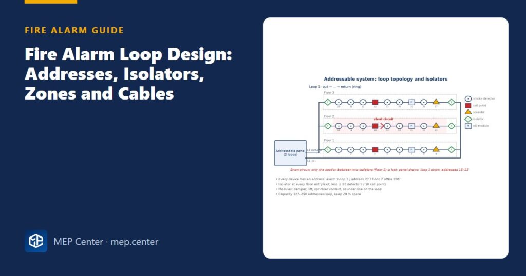
An addressable fire alarm loop can carry hundreds of devices on one pair of wires – which is exactly why a single short circuit, a full address list or a long thin cable can take a whole building’s detection down. Good loop design is mostly bookkeeping: an address budget, isolators in the right places, zones that make sense to a fire fighter, and cables that survive the fire. This guide walks you through it with a two-loop worked example.
- A loop leaves the panel, passes every device and returns to the panel; a single open circuit is tolerated, a short circuit is not – hence isolators.
- Loops hold 127–250 addresses depending on the manufacturer; design to 80 % at most and keep 20 % spare.
- Isolator rule: one short or open circuit must not disable more than 32 detectors or 10 manual call points in a detection zone.
- Detection zones: every storey at least one zone, ≤ 2000 m², search distance ≤ 60 m.
- Run the outgoing and return legs on different routes; use fire-resistant cable (at least 30 min) – FE180 PH90 where the loop carries alarm devices.
- Battery: Ah = 1.25 × (Istandby × Tstandby + Ialarm × Talarm).
How a loop works
In an analogue addressable system every detector, call point, sounder and module has its own address. The cable starts at the panel’s loop output, visits each device in turn and comes back to the loop input. Because the panel can feed the line from both ends, a single break does not lose any device. A short circuit is different: it collapses the voltage on the whole line. Short-circuit isolators (EN 54-17) split the loop into sections, so a short only takes out the section between two isolators.
Conventional systems work differently: each zone is a two-wire radial circuit wired in-out through up to 32 devices, ending at an end-of-line resistor so the panel can see an open circuit. There are no isolators; separate sounder circuits keep alarms alive. If you are still deciding between the two, read conventional vs addressable fire alarm systems first.
The address budget
Add up everything that takes an address: detectors, call points, input/output modules, and loop-powered sounders and beacons. Then:
- Use no more than 80 % of the loop’s capacity. The spare 20 % absorbs revisions, tenant fit-outs and the extra devices that appear on site.
- Check loop current, not just addresses. Add the standby and alarm current of every device; loop-powered sounders raise the alarm current quickly.
- Check length and resistance against the manufacturer’s limits – typically 2–3 km with 1.5 mm² cable and a total loop resistance around 40–50 Ω.
- Keep a loop within one fire compartment or one group of floors where possible, and protect every compartment crossing with isolators.
Number of loops = ⌈Naddresses ÷ (Cloop × 0.8)⌉, where N is the total address count and Cloop the loop capacity in addresses. Example: 414 addresses on a 250-address panel → 414 ÷ 200 = 2.07 → 3 loops (choose 4 if growth is likely).
Isolators: where and how many
The governing rule: after any single short or open circuit, you may lose no more than 32 detectors or 10 call points within one detection zone. In practice:
- An isolator at the entry and exit of every detection zone – an isolating call point at the zone boundary does the job.
- Isolators at every floor crossing and compartment boundary.
- Extra isolators inside a zone whenever a section holds more than 32 detectors.
- Isolating bases (an isolator in every device) remove the counting problem altogether for a small extra device cost.
- Alarm devices: after any single fault at least one sounder must still work – spread sounders over different isolated sections.
Zones and call points
Addressing does not abolish zones – the fire service still needs to know where to go. In a conventional system a zone is a physical circuit; in an addressable system it is a software group, with the same rules:
- Floor area per detection zone ≤ 2000 m²; every storey is at least one zone.
- A zone covering more than one fire compartment must follow compartment boundaries and stay ≤ 300 m².
- Search distance inside the zone ≤ 60 m; zones with more than 5 rooms need remote indicators or room-level indication.
- Void and underfloor detectors identifiable separately.
- Alarm zones follow the evacuation strategy and compartment boundaries; an alarm zone may contain several detection zones, never the reverse.
Manual call points go on escape routes, next to every door onto an escape stair and at every final exit, with a walking distance of about 30 m to the nearest one and the centre at 1.2 m (0.9–1.4 m). NFPA 72 asks for a pull station within 1.5 m (5 ft) of each exit door, a maximum travel distance of 61 m (200 ft) and the operable part at 1.07–1.22 m (42–48 in).
Loop capacities, cable limits and the zone, isolator and battery rules here follow our fire alarm course (CEN/TS 54-14 and NFPA 72, 2022). They are typical — verify with the edition adopted locally, the authority having jurisdiction and the selected panel manufacturer.
Worked example: two loops for a three-storey office
Inputs. Ground + 2 office floors, 600 m² each, plus a 600 m² basement car park. Security staffed 24/7. Loop capacity of the selected panel: 127 addresses.
Step 1 – addresses per area.
| Area | Detectors | Call points | Sounders / beacons | Modules | Total |
|---|---|---|---|---|---|
| Each office floor | 34 (17 room + 17 ceiling void) | 3 | 10 | 2 | 49 |
| Basement car park | 22 (20 heat + 2 multi-sensor) | 2 | 4 | 4 | 32 |
| Building | 3 × 49 + 32 = 179 |
Step 2 – number of loops. Usable per loop = 127 × 0.8 = 101.6 → 101 addresses. 179 ÷ 101.6 = 1.76 → 2 loops.
Step 3 – split by floors. Loop 1 = basement + ground = 32 + 49 = 81 (81 ÷ 127 = 64 %). Loop 2 = floors 1 + 2 = 49 + 49 = 98 (98 ÷ 127 = 77 %). Both ≤ 80 % ✓.
Step 4 – isolator check. With isolators only at floor entry and exit, one floor section holds 34 detectors – a short there would lose 34 > 32 ✗. Add a mid-floor isolator: section A = 17 room detectors + 2 call points + 5 sounders; section B = 17 void detectors + 1 call point + 5 sounders. Each section ≤ 32 detectors and ≤ 10 call points ✓, and each keeps its own sounders, so one fault never silences a floor ✓. Basement: 22 detectors and 2 call points between its isolators ✓.
Step 5 – battery. Istandby = 0.5 A, Ialarm = 3.2 A, staffed → 24 h + 30 min. Ah = 1.25 × (0.5 × 24 + 3.2 × 0.5) = 1.25 × (12 + 1.6) = 17.0 Ah → 2 × 12 V 18 Ah.
Sanity check. 81 + 98 = 179 ✓. Both loops leave more than 20 % spare (46 and 29 addresses). If the client later adds a fourth floor (49 addresses), neither loop can take it within 80 % – a third loop or a panel with spare loop slots is the honest answer, so state the spare capacity in the design report.
Cables and voltage drop
Fire alarm cables must keep working through fire and fire-fighting for at least 30 minutes, or be protected for that time. Typical European selection:
| Circuit | Typical cable |
|---|---|
| Detection loop (detectors, call points, input modules) | Screened, halogen-free fire alarm cable, 0.8 mm conductors; 1.5 mm² on long loops |
| Loop that also carries sounders, beacons or control modules | Same, rated FE180 PH90 (180 min function, 90 min circuit integrity) |
| Sounder / beacon lines, 24 V DC supplies | 2 × 1.5 mm² fire-resistant (FE180), checked for voltage drop |
| Damper control and position monitoring | 4 × 1.5 or 6 × 1.5 mm² FE180 PH90 |
Earth the screen at one point only – the panel. Keep alarm cables off power trays unless a separator is fitted, use fire-resistant cable in all vertical shafts, and remember cable in ceiling voids adds to the fire load used to decide void detection (see smoke and heat detector spacing).
On 24 V DC lines at least 20–21 V must remain at the farthest device:
ΔU = 2 × L × I × ρ ÷ A
ΔU is the voltage drop (V), L the one-way length (m), I the current (A), ρ = 0.0175 Ω·mm²/m for copper at 20 °C (low-current alarm cables barely warm up; power cables use about 0.0225 at operating temperature) and A the conductor cross-section (mm²). A sounder line of 100 m, 0.5 A, 1.5 mm²: 2 × 100 × 0.5 × 0.0175 ÷ 1.5 = 1.17 V (about 5 %) – fine. At 250 m it becomes 2.92 V (12 %): go to 2.5 mm² or move the power supply closer. For the general method see our cable sizing and voltage drop guide.
Standby power
Batteries must run the system for 24 h standby plus 30 min alarm where the building is continuously attended or faults are transmitted immediately, and 72 h + 30 min where it is not. The 1.25 factor covers ageing and temperature. If the batteries do not fit the panel cabinet, use an external EN 54-4 power supply whose fault output is monitored on the loop. NFPA 72 asks for 24 h standby + 5 min alarm (15 min with emergency voice communication).
Drawing the loop
For each loop show: panel output, devices in order with type symbol and address, isolators, floor and compartment crossings, and the return. On plans write the loop and address next to every symbol (for example L2-047) – the panel programming and the device labels use the same numbers. The riser diagram shows each loop, its floors, isolators, cable label and power supplies. In NFPA terms a return loop is Class A, a single-ended circuit Class B, and an isolated loop that keeps working after a single short Class X; partial-evacuation buildings may need 2-hour survivability for notification circuits.
Common mistakes
- Filling loops to 100 % at design stage – the first revision then needs a new loop.
- Isolators only at floor boundaries on floors with more than 32 detectors.
- All sounders of a floor in one isolated section, so one fault silences the floor.
- Outgoing and return cables in the same tray or shaft.
- Counting addresses but not loop current with loop-powered sounders.
- Non-fire-resistant cable on loops that carry alarm and control devices, or in shafts.
- Screen earthed at both ends; alarm cables loose on power trays.
- Zone names on the panel that mean nothing to a fire fighter.
Quick checklist
- Address count per loop ≤ 80 % of capacity; spare stated in the report.
- Loop current and length within manufacturer limits; voltage drop checked.
- Isolators at zone, floor and compartment boundaries; ≤ 32 detectors / ≤ 10 call points per section.
- Sounders spread across sections.
- Zones: per storey, ≤ 2000 m², ≤ 60 m search; meaningful names.
- Call points at stair doors and exits, within about 30 m walking distance, 1.2 m high.
- Fire-resistant cables; return leg on a separate route.
- Battery calculation attached; external supplies monitored.
- Loop diagram with addresses matches plan labels.
Fire Detection and Alarm System Design
Detector selection and layout, loops, panels, voice alarm and real DXF projects to EN 54-14 and NFPA 72.
Modules 1–3 are free, no account needed · full course €8,00 one-time
FAQ
How many devices can be on one fire alarm loop?
Typically 127–250 addresses depending on the manufacturer. Design to no more than 80 % of that and also check the loop current and cable length limits.
Where should short-circuit isolators be placed?
At the entry and exit of every detection zone, at floor and compartment crossings, and inside any section that would otherwise hold more than 32 detectors or 10 call points.
Why should the loop return on a different route?
A loop survives a single break because it is fed from both ends. If both legs share one tray or shaft, a single damaged route can cut both sides at once and lose every device beyond the damage.
How do I size the fire alarm battery?
Use Ah = 1.25 × (standby current × standby time + alarm current × alarm time). With 0.5 A standby, 3.2 A alarm and 24 h + 30 min, that gives 17 Ah, so 2 × 12 V 18 Ah batteries.
More Fire Alarm articles
- Optical Beam Smoke Detectors: Where and How to Place Them
- Aspirating Smoke Detection: When and How
- EN 54-14 vs NFPA 72: Fire Alarm Design Differences
- How to Write a Fire Alarm Cause and Effect Matrix
- Conventional vs Addressable Fire Alarm Systems Explained
- Manual Call Point Placement: Distances, Heights, Exits