
The earthing system decides how much current flows when a live conductor touches a metal case — and therefore whether an ordinary breaker can clear the fault or you need an RCD. Get it wrong and every disconnection-time check on the project is built on sand.
This guide explains TN-S, TN-C-S, TT and IT in plain terms, shows what each means for your protective devices, and works through the same circuit on TN-C-S and TT so you can see the difference in numbers.
- The two letters say how the source is earthed (T = direct to earth, I = isolated) and how exposed metal parts are earthed (N = via the supply’s neutral/PE, T = local electrode).
- TN systems give a low-impedance fault loop: hundreds of amps flow, so an MCB can disconnect on its own if Zs is low enough.
- TT systems return the fault current through the soil: only a few amps flow, so RCDs are essential.
- TN-C-S (PME) is the most common utility supply but has a broken-PEN risk; outdoor and EV supplies often need special measures or a TT island.
- IT systems keep running after the first fault and raise an alarm; they suit operating theatres and critical processes.
- Typical disconnection time at 230 V for final circuits up to 32 A: 0.4 s on TN, 0.2 s on TT.
Reading the letters
First letter — the source: T (terra) means the transformer star point is connected directly to earth; I means it is isolated from earth or earthed through a high impedance.
Second letter — the installation’s exposed metal parts: N means they are connected to the earthed point of the source through a protective conductor supplied with the network; T means they go to a local earth electrode, independent of the source earth.
After the dash (TN only): S = separate neutral (N) and protective (PE) conductors; C = combined in one PEN conductor; C-S = combined in the supply network, separated at the origin of the installation.
The four systems in practice
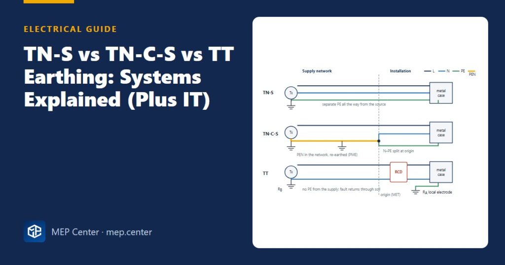
TN-S — separate PE from the source
The supply provides a separate protective conductor (often the cable sheath or a dedicated core) all the way from the transformer. Fault loops are low impedance, and there is no PEN to break. You get TN-S inside any building with its own transformer: the MV/LV substation is earthed, and from the main LV board onwards you run five wires (L1, L2, L3, N, PE). It is the preferred system for commercial and industrial buildings.
TN-C-S — combined in the network, separated in the building
The utility runs a combined PEN conductor, earthed at many points along the network (protective multiple earthing, PME). At the origin of your installation the PEN is split into N and PE, and from there on they must never be joined again. It is the most common public supply in many countries because it gives low loop impedance cheaply.
The weak point is a broken PEN upstream: the installation’s metalwork can rise towards line voltage, and everything bonded to the MET rises with it. That is why many codes restrict PME for supplies to outdoor locations, EV charge points, caravans, boats, petrol stations and construction sites, and why main bonding conductors on PME supplies are sized to the supply neutral. The usual answers are an open-PEN detection device or a TT island with its own electrode.
TT — local electrode, RCDs essential
The installation has no protective conductor from the supply; exposed metal parts are connected to a local earth electrode. The fault current must pass through two electrodes and the soil, so it is only a few amps — far too little to trip an MCB magnetically. Protection relies on RCDs. TT is common in rural networks, for outbuildings and as an island on PME supplies.
IT — isolated source, keeps running
The source is not earthed (or earthed through a high impedance). A first fault to earth produces almost no current, so nothing disconnects; an insulation monitoring device raises an alarm and maintenance finds the fault. A second fault on another phase must disconnect, like TN or TT. IT is used where an unplanned shutdown is dangerous or expensive: operating theatres and intensive care (through a medical isolating transformer), process plants and some marine installations.
TN-C — the one to avoid in buildings
A PEN conductor throughout the installation mixes load current with the protective path. It is generally permitted only in fixed cables of 10 mm² copper or larger, so building designers separate N and PE at the origin and stay TN-S from there.
| System | Typical external loop impedance Ze | Earth-fault current | Main protection for shock | Typical use |
|---|---|---|---|---|
| TN-S | ≈ 0.8 Ω | Hundreds of A | MCB/fuse (Zs check), RCD for sockets | Own transformer, commercial, industrial |
| TN-C-S (PME) | ≈ 0.35 Ω | Hundreds of A | MCB/fuse (Zs check), RCD for sockets | Public LV supply to homes and shops |
| TT | ≈ 21 Ω plus your electrode | A few A | RCD (RA × IΔn ≤ 50 V) | Rural supplies, outbuildings, EV/outdoor islands |
| IT | — | First fault: mA | Insulation monitoring + second-fault disconnection | Operating theatres, critical processes |
The Ze values, disconnection times, conductor sizes and electrode limits in this article are typical (common utility-declared maxima in BS 7671 practice) — verify with the edition adopted locally and with the values declared by your utility.
Disconnection times and the two key checks
Automatic disconnection of supply (ADS) is the main protection against indirect contact. For 230 V systems, typical maximum times are:
- Final circuits up to 32 A: 0.4 s on TN, 0.2 s on TT (some editions extend this to 63 A for socket-outlet circuits).
- Distribution circuits and larger final circuits: 5 s on TN, 1 s on TT.
TN check: Zs × Ia ≤ U0. Zs is the fault-loop impedance (Ω) = Ze + R1 + R2, where R1 and R2 are the line and protective conductor resistances of the circuit at operating temperature; Ia is the current that operates the device within the required time (A) — for an MCB, its upper magnetic threshold (5 × In for type B, 10 × In for type C); U0 is the line-to-earth voltage, 230 V. Many designers apply a factor of 0.95 to U0 to allow for supply voltage tolerance.
TT check: RA × IΔn ≤ 50 V. RA is the resistance of the local electrode plus protective conductor (Ω), and IΔn the rated residual operating current of the RCD (A). With a 30 mA RCD the limit is 50 / 0.03 ≈ 1667 Ω, but an electrode above about 200 Ω is usually considered unstable (it changes with season and moisture), so design for well below that.
Worked example: the same circuit on TN-C-S and TT
Inputs — 230 V radial socket circuit, 30 m, 2.5 mm² line and 1.5 mm² protective conductor (copper), protected by a B20 MCB. Typical conductor resistances at 20 °C: 7.41 mΩ/m (2.5 mm²) and 12.10 mΩ/m (1.5 mm²); multiply by 1.20 for operating temperature. Disconnection within 0.4 s (TN) or 0.2 s (TT).
Case A — TN-C-S, Ze = 0.35 Ω
Step 1 — circuit resistance: R1 + R2 = (7.41 + 12.10) × 30 / 1000 = 0.585 Ω at 20 °C → × 1.20 = 0.70 Ω.
Step 2 — loop impedance: Zs = 0.35 + 0.70 = 1.05 Ω.
Step 3 — maximum allowed: Ia = 5 × 20 = 100 A; Zs,max = 0.95 × 230 / 100 = 2.19 Ω. 1.05 Ω ≤ 2.19 Ω ✓.
Step 4 — fault current: If = 230 / 1.05 ≈ 219 A, more than twice the 100 A that guarantees magnetic tripping. The MCB clears the fault in well under 0.1 s.
Step 5 — maximum length on this supply: (2.19 − 0.35) / (19.51 × 1.20 / 1000) = 1.84 / 0.0234 ≈ 78 m.
Case B — TT, local electrode RA = 60 Ω (measured), source electrode RB assumed 10 Ω
Step 1 — fault current: If ≈ 230 / (60 + 10 + 0.70) ≈ 3.3 A. The B20 MCB needs 100 A to trip magnetically — it will not disconnect.
Step 2 — add a 30 mA RCD (or RCBO): RA × IΔn = 60 × 0.03 = 1.8 V ≤ 50 V ✓. The fault current (3.3 A) is over 100 times IΔn, so the RCD trips in tens of milliseconds, well inside 0.2 s.
Step 3 — electrode stability: 60 Ω is far below the 200 Ω guidance ✓. An upstream time-delayed 100 mA RCD would also pass: 60 × 0.1 = 6 V.
Sanity check — the same cable gives 219 A on TN-C-S and about 3 A on TT: a factor of roughly 65, which is why TT designs never rely on MCBs for shock protection. Case A also matches the familiar rule that a B20 radial in 2.5/1.5 mm² cable is good for several tens of metres on a PME supply.
Which system will you have?
Usually the supply decides: a public LV supply is mostly TN-C-S (sometimes TT), and a building with its own MV/LV substation is TN-S from the main board. You choose actively in three cases:
- TT island on a PME supply for EV chargers, outdoor equipment or outbuildings where a broken PEN would be dangerous.
- IT for medical group 2 locations and processes that must ride through a first fault.
- TN-S instead of TN-C-S inside your own network: always separate N and PE at the main board.
Once the system is known, size cables and protective devices to match: the fault-loop check sets the maximum length of each MCB-protected circuit (see our MCB selection and discrimination guide), and the same lengths drive voltage drop. On unbalanced boards the neutral also carries the difference current, so keep boards balanced as shown in phase balancing in panel schedules.
How it looks on the drawing
- The single-line diagram states the earthing system and Ze at the origin (for example “TN-C-S, Ze 0.35 Ω”).
- The N–PE link is shown at the main board only, with the main earthing terminal and main bonding conductors to water, gas and structural steel.
- Each circuit on the schedule lists its protective conductor size and the calculated Zs or maximum length.
Common mistakes
- Re-joining N and PE downstream of the origin (in a sub-board or at an appliance), which puts load current on the protective conductors and blinds RCDs.
- Assuming TN values on a TT supply and relying on MCBs for shock protection.
- Using the 20 °C conductor resistance in the Zs check instead of the operating-temperature value.
- Supplying EV chargers or outdoor equipment from a PME earth without the required measures.
- Designing a TT electrode to the 1667 Ω arithmetic limit instead of a stable value well under 200 Ω.
- Not stating the earthing system and Ze on the single-line diagram, so the reviewer cannot check any disconnection time.
Quick checklist
- Earthing system and Ze confirmed with the utility (or calculated for your own transformer).
- N and PE separated at the origin and never joined again.
- Every MCB/fuse circuit: Zs ≤ Zs,max for the required disconnection time.
- TT: RCD on every circuit, RA × IΔn ≤ 50 V, electrode resistance stable and recorded.
- Special locations (EV, outdoor, medical) checked against PME and IT requirements.
- Main bonding conductors sized and shown on the drawings.
Electrical Power Systems Design for Buildings
35 modules from the MV connection to the socket: transformers, short circuit, protection and selectivity, cable sizing, boards, generators, earthing, surge and lightning protection. Includes 50 % off TEKHAT.
Modules 1–3 are free, no account needed · full course €15,00 one-time
FAQ
What is the difference between TN-S and TN-C-S?
In TN-S the supply provides a separate protective conductor all the way from the transformer. In TN-C-S the network uses one combined PEN conductor, which is split into neutral and protective conductors at the origin of the installation. Both give low fault-loop impedance, but TN-C-S carries a broken-PEN risk.
Why does a TT system need RCDs?
In a TT system the fault current returns through the soil between two earth electrodes, so it is typically only a few amps. That is far below the current needed to trip an MCB magnetically, so an RCD is the device that disconnects the fault in time.
What earth electrode resistance is acceptable for TT?
The condition is electrode resistance times the RCD rated residual current not exceeding 50 V, which allows about 1667 ohms with a 30 mA RCD. In practice an electrode above about 200 ohms is considered unstable, so aim well below that.
Where is an IT earthing system used?
IT is used where a first earth fault must not cause a shutdown, such as operating theatres, intensive care units and critical industrial processes. An insulation monitoring device raises an alarm on the first fault, and a second fault must disconnect.
Can I supply an EV charger from a PME (TN-C-S) earth?
Often only with extra measures, such as an open-PEN detection device built into the charger or a separate TT earth electrode for the charger. Check the rules of the edition adopted locally before deciding.
TEKHAT – Single-Line Diagram & Load Schedule
Draw panel single-line diagrams and load schedules in minutes, with breaker, RCD and cable sizing. Buyers of the Electrical Power Systems Design course get 50 % off.
Free install from the Microsoft Store · 30-day trial · licence 20 € for all your devices or €15 per computer on our site
More Electrical articles
- IEC vs NEC: Earthing, Grounding and Bonding Terms Compared
- 10 Common Mistakes on Single-Line Diagrams
- Emergency Lighting: Quick Design Rules (EN 1838 / NFPA 101)
- Lightning Protection Basics: Rolling Sphere and Mesh Method
- PV Systems: DC Isolation, Fuses and Earthing Basics
- How to Measure Earth Electrode Resistance (Fall-of-Potential)