
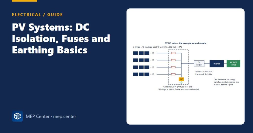
The DC side of a PV system is unusual. It cannot be switched off while the sun shines, its fault current is barely higher than its operating current, and its voltage rises on cold mornings. Protection copied from AC practice, with a single breaker sized for the load, does not work there. These are the basics a building services engineer needs to check a PV design.
Five things that make PV DC different
- Always live: modules produce voltage in daylight. Opening the DC isolator does not make the cables between the array and the isolator dead.
- Low fault current: a short-circuited string delivers only about its Isc, slightly more than its operating current, so ordinary overcurrent devices never see a “fault”.
- Cold means higher voltage: Uoc rises about 0.29–0.30 % per K below 25 °C. Systems are limited to 1000 V or 1500 V DC.
- DC arcs do not self-extinguish: isolators, fuses and connectors must be rated for DC at the full voltage. Never unplug connectors under load.
- Reverse current: with strings in parallel, a faulted string can be fed by all the others.
Worked example: 4 strings of 18 modules
String voltage: 18 × 45.0 = 810 V at STC → × (1 + 0.0029 × 35) = 810 × 1.10 ≈ 892 V < 1000 V system limit ✓.
Design current per string: 1.25 × 13.0 = 16.3 A → 4 or 6 mm² PV cable (check derating and voltage drop).
Reverse current into a faulted string: up to (4 − 1) × 13 = 39 A > 25 A → string fuses needed.
Fuse: ≥ 1.5 × Isc = 19.5 A and ≤ 25 A → 20 A gPV, rated ≥ 1000 V DC, in both + and − (the array is not earthed).
SPD: Ucpv ≥ 892 V (or ≥ 1.2 × 810 = 972 V if no temperature data) → 1000 V PV SPD.
DC isolator: rated ≥ 1000 V DC, load-break, current ≥ 4 × 16.3 ≈ 65 A if one isolator serves all four strings.
IEC 60364-7-712 vs NEC 690 in short
| Item | IEC practice | NEC 690 practice |
|---|---|---|
| Design current | ≥ 1.25 × Isc STC | Maximum current 1.25 × Isc; conductors and overcurrent devices ≥ 125 % of that (≈ 1.56 × Isc) |
| Maximum voltage | Uoc at the lowest site temperature | Uoc corrected for the lowest expected temperature |
| String protection | gPV fuses when reverse current can exceed the module rating | Overcurrent protection per string unless the source cannot exceed the module rating |
| Isolation | DC isolator at the inverter; firefighter switch per national rules | PV disconnecting means; rapid shutdown on buildings |
| Earthing | Frames bonded; DC side usually not earthed, insulation monitored by the inverter | Equipment grounding of frames; ground-fault detection |
Checklist for the DC side
- Use PV cable rated 1.5 kV DC, single-core and double-insulated, with + and − run together to keep the loop area small.
- Use connectors of the same type and maker on both halves. Mixed brands are a known fire cause.
- Add a DC SPD at the inverter, and also at the array end when the DC cable is longer than about 10 m. See how to connect an SPD.
- Bond the frames and structure, and keep the separation distance from the lightning protection system, or bond to it and use Type 1+2 SPDs. See lightning protection basics.
- On the AC side, use a type B RCD unless the inverter cannot feed DC fault current (simple separation or a maker declaration). See RCD types.
- Label everything: “PV DC – live in daylight”, plus isolation points and dual supply warnings at the board.
Typical values — verify with the edition adopted locally and with the module and inverter data sheets.
Electrical Power Systems Design for Buildings
35 modules from the MV connection to the socket: transformers, short circuit, protection and selectivity, cable sizing, boards, generators, earthing, surge and lightning protection. Includes 50 % off TEKHAT.
Modules 1–3 are free, no account needed · full course €15,00 one-time
FAQ
When are string fuses needed in a PV system?
When three or more strings are connected in parallel and the reverse current that the other strings can feed into a faulted string exceeds the module’s maximum series fuse rating. With one or two strings it normally cannot, so fuses are usually not needed.
How do I find the maximum DC voltage of a PV string?
Multiply the module Uoc by the number of modules, then correct it to the lowest site temperature using the module’s temperature coefficient (about +0.29–0.30 % per K below 25 °C). This is typically 10–15 % above the STC value (use 1.2 × Uoc STC if no temperature data is available) and must stay below the 1000 V or 1500 V system limit.
Which RCD type does a PV inverter need?
Type B, unless the inverter maker states that the inverter cannot feed DC fault current into the AC side, for example because of simple separation. In that case type A is acceptable.
TEKHAT – Single-Line Diagram & Load Schedule
Draw panel single-line diagrams and load schedules in minutes, with breaker, RCD and cable sizing. Buyers of the Electrical Power Systems Design course get 50 % off.
Free install from the Microsoft Store · 30-day trial · licence 20 € for all your devices or €15 per computer on our site
More Electrical articles
- How to Measure Earth Electrode Resistance (Fall-of-Potential)
- EV Charger Installation: An Electrical Checklist
- Standby Generator Sizing: A Quick Method That Works
- Motor Starting: DOL, Star-Delta, Soft Starter or VFD
- RCD Types AC, A, F and B: Which One Where
- TN-S vs TN-C-S vs TT Earthing: Systems Explained (Plus IT)