
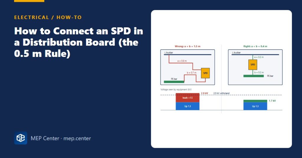
Most surge protective devices that fail to protect anything are not faulty. They are simply wired with long, looping leads, and those leads add more voltage than the SPD removes.
Why the lead length matters so much
A surge current rises by thousands of amperes per microsecond. Every metre of conductor has an inductance of roughly 1 µH, and the voltage across it is L × di/dt. A handy rule: about 1 kV per metre of lead at 10 kA/µs. That voltage adds directly to the SPD’s own protection level Up, so the equipment sees:
Up,eff ≈ Up + lead voltage
Equipment on a 230/400 V installation is typically rated to withstand 2.5 kV (category II, ordinary appliances) or 1.5 kV (category I, sensitive electronics). If the leads push Up,eff above that, the SPD conducts exactly as designed and the equipment is still damaged.
Up,eff ≈ 1.3 + 1.5 = 2.8 kV — above the 2.5 kV withstand. Protection lost.
Same SPD, mounted next to the incomer and the PE bar: a + b = 0.4 m → Up,eff ≈ 1.3 + 0.4 = 1.7 kV. At the 0.5 m limit it would be 1.8 kV. Both pass with margin.
Step by step: connecting a Type 2 SPD in a board
- Plan the position before the board is built. Put the SPD next to the incoming device and close to the PE bar. Why: the 0.5 m rule is decided at layout stage, not on site.
- Check the earthing system and choose the configuration. On TN systems use Uc ≥ 1.1 × U0 (≥ 253 V, typically 275 V devices). On TT use the “3+1” arrangement: L–N varistors plus an N–PE spark gap. Why: the wrong configuration can overheat or leave a mode unprotected.
- Add the back-up protection. Fit the fuse or breaker the SPD maker specifies in the SPD branch, unless the upstream device is already within the maker’s limit. Why: an SPD at end of life can fail short-circuit; the back-up removes it without tripping the incomer.
- Run the line leads short and straight. Count the lead through the back-up device as part of a. Why: every centimetre adds voltage during the surge.
- Take the earth lead directly to the PE bar, not to the enclosure door or a remote terminal, and bond that bar to the main earthing terminal. Why: b counts as much as a.
- Keep the line and earth leads close together and away from outgoing cables. Why: a small loop area means less induced voltage and less coupling into protected circuits.
- Use the right cross-section: ≥ 6 mm² Cu for Type 2, ≥ 16 mm² Cu for Type 1. Why: the leads must carry the surge current without damage.
- Use a V-connection if 0.5 m is impossible. Run the incoming conductor into the SPD terminal and out again to the load. Why: the stub disappears, so the lead length in the surge path is practically zero.
- Wire the status contact to the BMS or a local lamp. Why: a disconnected SPD gives no visible symptom until the next surge.
Typical values — verify with the edition adopted locally and with the SPD maker’s instructions.
Type 1, Type 2, Type 3 in one paragraph
A Type 1 SPD (10/350 µs test) goes at the origin when the building has an external lightning protection system or an overhead supply; Iimp of at least 12.5 kA per pole is a common default. A Type 2 (8/20 µs, In ≥ 5 kA, 20 kA typical) is used at the origin without LPS and at sub-boards. A Type 3 sits within about 10 m of sensitive equipment. Between Type 1 and Type 2 you need about 10 m of cable for decoupling, or a combined device coordinated by the maker. The same short-lead rules apply to all three.
Checks before you close the board
- Measure a and b with a tape. Do not estimate them from the drawing.
- The SPD earth goes to the PE bar, not to the neutral bar (TN-S) and not to the door.
- Disconnect the SPD (or test at 250 V) before insulation-resistance testing, then reconnect it.
- The SPD, its Up and its back-up device are shown on the single-line diagram.
Earthing quality matters too. If the earthing arrangement itself is unclear, start with TN, TT and IT earthing systems explained. For back-up device selection, see MCB selection and discrimination.
Electrical Power Systems Design for Buildings
35 modules from the MV connection to the socket: transformers, short circuit, protection and selectivity, cable sizing, boards, generators, earthing, surge and lightning protection. Includes 50 % off TEKHAT.
Modules 1–3 are free, no account needed · full course €15,00 one-time
FAQ
What is the 0.5 m rule for SPDs?
The total length of the conductors from the line to the SPD and from the SPD to the earth bar (a + b) should not exceed 0.5 m, and never 1 m. Each metre of lead adds roughly 1 kV to the voltage the equipment sees during a surge.
What cable size should I use to connect an SPD?
Typically at least 6 mm² copper for a Type 2 SPD and at least 16 mm² copper for a Type 1 SPD. Always check the maker’s instructions, which may ask for more.
Does an SPD need its own fuse or breaker?
Yes, unless the upstream protective device is already within the maximum back-up rating given by the SPD maker. The back-up device disconnects an SPD that fails short-circuit without tripping the whole installation.
What is a V-connection for an SPD?
The incoming conductor is wired into the SPD terminal and continues out of it to the load, so there is no stub lead. It is the preferred solution where a short a + b cannot be achieved.
TEKHAT – Single-Line Diagram & Load Schedule
Draw panel single-line diagrams and load schedules in minutes, with breaker, RCD and cable sizing. Buyers of the Electrical Power Systems Design course get 50 % off.
Free install from the Microsoft Store · 30-day trial · licence 20 € for all your devices or €15 per computer on our site
More Electrical articles
- Emergency Lighting: Quick Design Rules (EN 1838 / NFPA 101)
- Phase Balancing in Panel Schedules: Measure and Fix Unbalance
- UPS Sizing: kVA, kW and Battery Autonomy in Practice
- Cable Tray Sizing: Fill, Spacing and Derating in Practice
- TN-S vs TN-C-S vs TT Earthing: Systems Explained (Plus IT)
- RCD Types AC, A, F and B: Which One Where