
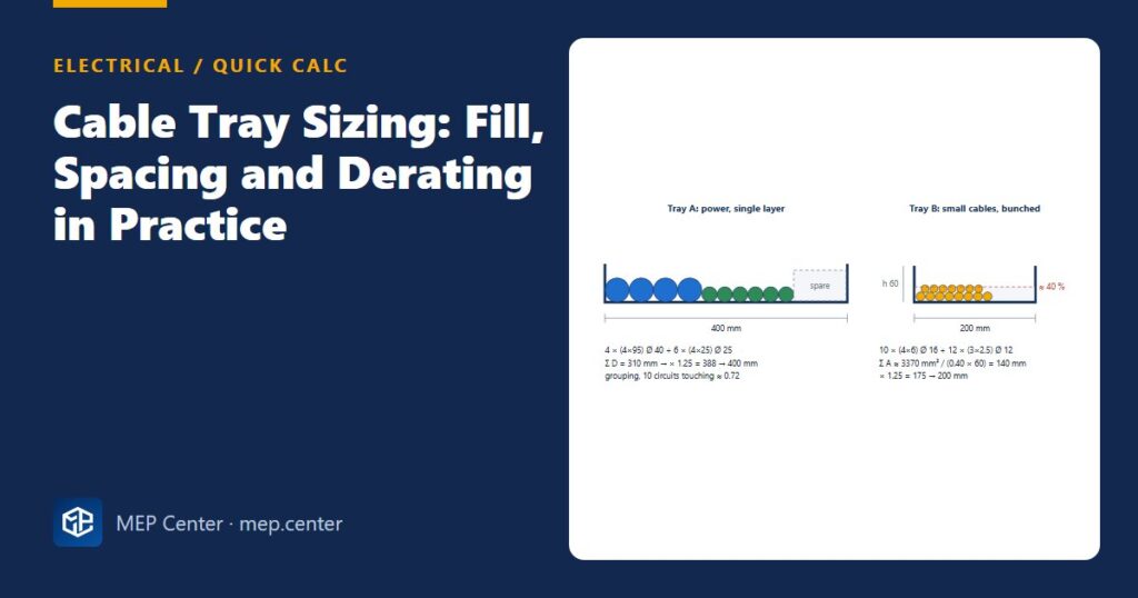
A tray that is “big enough” on the drawing can still be wrong in two ways. Cables piled on it no longer carry the current they were sized for, or the tray sags between supports under the weight. Width, fill, span and derating have to be checked together.
The two sizing methods
Large power cables: single layer. They keep the “free air / perforated tray” rating (installation method E) only when laid side by side. The width follows from the diameters:
W ≥ (Σ D) × (1 + spare) — D = overall cable diameter (mm) from the cable data sheet; spare typically 0.20–0.25.
Small cables (control, lighting, small power): bunched. They are rated with the bunched grouping factor anyway, so area is what counts:
W ≥ Σ A / (fill × h) × (1 + spare) — A = π D² / 4 per cable (mm²); fill ≈ 0.40; h = usable side height of the tray (mm).
Worked example: a riser with two trays
Σ D = 4 × 40 + 6 × 25 = 160 + 150 = 310 mm. With 25 % spare: 310 × 1.25 = 388 mm → 400 mm tray.
Weight: 4 × 4.4 + 6 × 1.3 ≈ 25 kg/m, ≈ 32 kg/m with spare → check against the maker’s safe working load for a 400 mm tray at the chosen span.
Grouping: 10 circuits in a single layer, touching, on perforated tray → factor ≈ 0.72. The cable sizes must already include it.
Tray B (small cables). 10 × (4 × 6 mm²), Ø ≈ 16 mm → A ≈ 201 mm² each; 12 × (3 × 2.5 mm²), Ø ≈ 12 mm → A ≈ 113 mm² each.
Σ A = 2010 + 1356 ≈ 3370 mm². Width = 3370 / (0.40 × 60) ≈ 140 mm; × 1.25 = 175 mm → 200 mm tray.
Two trays rather than one wide tray also separate large feeders from small power and control cables. You get that segregation without extra cost.
Rules of thumb
| Item | Typical value |
|---|---|
| Spare capacity on trays | 20–25 % |
| Fill for bunched small cables | ≈ 40 % of usable section |
| Support span: tray / ladder / wire basket | 1.5–2.0 m / 3–6 m / 1.2–1.5 m |
| Deflection limit used in load tests | ≈ span / 100 |
| Free space above a tray | ≥ 300 mm |
| Grouping, single layer touching on perforated tray | 2: 0.88 · 3: 0.82 · 4: 0.77 · 6: 0.73 · ≥ 9: 0.72 |
| Single layer spaced by ≥ 1 cable diameter | ≈ 1.0 for a few circuits |
| Bunched cables (circuits) | 2: 0.80 · 3: 0.70 · 4: 0.65 · 6: 0.57 · 9: 0.50 |
| Min. bending radius: unarmoured LV / armoured LV | 6–8 × D / 10–12 × D |
Typical values — verify with the edition adopted locally and with the tray and cable makers’ data.
Derating: where tray sizing meets cable sizing
If the 0.72 grouping factor makes a feeder jump a size, you have three options. Space the cables by one diameter (factor close to 1.0, but the tray gets wider), split the circuits over two trays, or accept the bigger cable. Watch the route too. If a feeder leaves the perforated tray and runs through a closed trunking for part of its length, its rating can drop by 20–35 %. A 95 mm² XLPE cable goes from about 298 A to about 201 A. The worst section of the route sets the rating. For the cable side of this check, see cable sizing and voltage drop and the free voltage drop calculator.
Things reviewers spot
- Large cables drawn “stacked” on a tray sized by area. They then lose the single-layer rating.
- No weight check. Ladders are needed far sooner than people expect once 95 mm² and larger cables appear.
- Tray bends that are smaller than the bending radius of the largest cable (12 × D for a Ø 45 mm armoured cable is 540 mm).
- Trays drawn under pipe joints or through ducts. Coordinate in the model; see the MEP clash checklist.
- Missing bonding jumpers between tray sections where the tray is used as a protective path.
Electrical Power Systems Design for Buildings
35 modules from the MV connection to the socket: transformers, short circuit, protection and selectivity, cable sizing, boards, generators, earthing, surge and lightning protection. Includes 50 % off TEKHAT.
Modules 1–3 are free, no account needed · full course €15,00 one-time
FAQ
What is the maximum fill for a cable tray?
For bunched small cables, a common design limit is about 40 % of the usable cross-section, plus 20–25 % spare width. Large power cables are not sized by fill at all. They are laid in a single layer and sized by the sum of diameters.
How do I calculate cable tray width?
For single-layer power cables, add the cable diameters and multiply by 1.2–1.25 for spare. For bunched small cables, divide the total cable area by 0.40 × the tray side height, then add the spare. Round up to the next standard width.
Does a cable tray reduce cable current rating?
The tray itself is a good installation method. Grouping is what reduces the rating. Ten cables touching in a single layer typically use a factor of about 0.72, while spacing them by one diameter brings it close to 1.0.
TEKHAT – Single-Line Diagram & Load Schedule
Draw panel single-line diagrams and load schedules in minutes, with breaker, RCD and cable sizing. Buyers of the Electrical Power Systems Design course get 50 % off.
Free install from the Microsoft Store · 30-day trial · licence 20 € for all your devices or €15 per computer on our site
More Electrical articles
- TN-S vs TN-C-S vs TT Earthing: Systems Explained (Plus IT)
- IEC vs NEC: Earthing, Grounding and Bonding Terms Compared
- Cable Sizing for Voltage Drop: Formula, Limits and Worked Example
- 10 Common Mistakes on Single-Line Diagrams
- MCB Selection and Discrimination: A Practical Design Guide
- Cable Gland Selection: Size, Armour, IP and Earthing