
Mains pressure rarely reaches the top floors of a building with enough left over for a shower to work properly. A booster pump set fixes that, but only if you size it for the real peak flow and the real head. Oversize it and the lower floors get hammered with pressure; undersize it and the top floor complains on day one.
Step 1: the design flow
The flow is the probable simultaneous demand, never the total of every outlet open at once. Use the same method you used to size the riser: loading units (EN 806-3) or water supply fixture units (IPC/UPC) converted to a peak flow with the code curve or table. Our guide on domestic water pipe sizing with fixture units walks through that conversion.
Add any continuous demand on top of the peak: cooling tower make-up, process water or irrigation that may run at the same time. Do not add fire water — fire pumps are a separate system with their own rules.
Step 2: the design head
Build the head from its parts, in metres of water (1 bar ≈ 10.2 m):
- Static lift (Hs) — vertical distance from the pump centreline to the highest (or furthest) outlet.
- Residual pressure (Hr) — the flow pressure you want at that outlet. Ordinary taps and mixers work from about 1.0 bar; thermostatic mixers, flush valves and some appliances need more. Use manufacturer data for the critical outlet.
- Pipe friction (Hf) — friction rate × equivalent length of the index run (straight pipe plus fittings) at the design flow.
- Component losses (Hc) — water meter, filter, check valves, any heat exchanger or softener on the line. Take these from manufacturer curves; they are often larger than the pipe friction.
- Suction side — if the pumps draw from a break tank, take the lowest water level and subtract that small positive head (or ignore it for safety). If the set boosts directly off the mains, where the water authority allows it, subtract the minimum guaranteed mains pressure.
H = Hs + Hr + Hf + Hc − Hinlet
Step 3: pump arrangement and power
Split the flow between duty pumps and add at least one standby of the same size (n + 1). Two or three duty pumps with variable speed drives give a near-constant discharge pressure and run efficiently at the low night-time flows that make up most of the operating hours. A small membrane vessel on the discharge stops the set cycling at zero demand; size it from the manufacturer’s method for the control type you choose.
Absorbed power per pump: P = ρ · g · Q · H / η, where ρ = 1000 kg/m³, g = 9.81 m/s², Q in m³/s, H in m and η the pump efficiency at the duty point. Then pick the next standard motor size.
Worked example
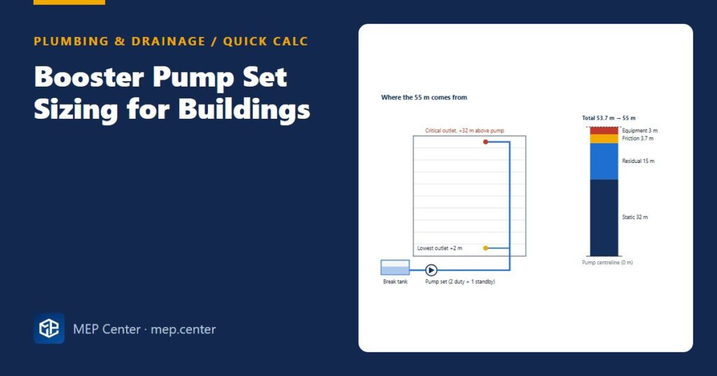
Building: 10-storey residential block, break tank in the basement, highest outlet 32 m above the pump centreline. Peak demand from loading units: 4.0 L/s.
- Static lift Hs = 32 m.
- Residual pressure at the top shower: 1.5 bar → Hr ≈ 15 m.
- Index run 80 m equivalent length at about 4 m per 100 m → 3.2 m; suction pipework 0.5 m → Hf = 3.7 m.
- Meter, filter and check valves from manufacturer data: Hc = 3 m.
- Tank low level ignored (conservative). H = 32 + 15 + 3.7 + 3 = 53.7 m → select 55 m.
- Arrangement: 2 duty + 1 standby, each 2.0 L/s (7.2 m³/h) at 55 m.
- Power per pump at η = 0.60: P = 1000 × 9.81 × 0.002 × 55 / 0.60 ≈ 1.8 kW → 2.2 kW motor.
Sanity check: the lowest outlet sits only 2 m above the pump, so it sees about (55 − 2) / 10.2 ≈ 5.2 bar static — above the usual 5 bar limit at draw-off points. The lower floors need a pressure reducing valve station or a separate low zone.
Rule-of-thumb checks
| Item | Typical value / practice |
|---|---|
| Residual pressure at critical outlet | 1.0–1.5 bar; more for flush valves and thermostatic mixers |
| Maximum static at draw-off (EN 806-2) | about 5 bar |
| Maximum static before a PRV is required (IPC) | 80 psi (about 5.5 bar) |
| Pressure zone height | roughly 30–35 m per zone in tall buildings |
| Standby capacity | at least one pump equal to the largest duty pump |
| Break tank | sized separately — see water storage tank sizing |
Typical values — verify with the edition adopted locally.
Common slips
- Using the sum of all fixture flows instead of the probable peak — the set ends up two or three times too big.
- Forgetting the meter, filter and softener losses; on small buildings they can exceed pipe friction.
- Selecting on the duty point only: check the shut-off head of fixed-speed pumps against the pipe and fitting pressure ratings.
- No standby pump, or a standby smaller than the duty pumps.
Ready-made drawings and tools for your next project
CAD block libraries, detail drawings and AutoCAD tools made by practising MEP engineers.
FAQ
How do I find the flow rate for a booster pump?
Convert the building’s loading units or fixture units into a probable peak flow with the method of your code (EN 806-3 or IPC/UPC), then add any continuous demands. Never use the sum of every outlet flowing at once.
How much pressure should be left at the top floor?
Typically 1.0 to 1.5 bar flow pressure at the most remote outlet. Flush valves, thermostatic mixers and some appliances need more, so check the manufacturer data for the critical outlet.
Do I always need a standby pump?
For any building where loss of water is a real problem, yes: provide at least one standby pump equal to the largest duty pump (n + 1), with automatic changeover and duty rotation.
Why do the lower floors need pressure reducing valves?
The pump must deliver enough head for the top floor, so the lowest floors see the top-floor pressure plus the height difference between them and the top floor. If static pressure there exceeds about 5 bar, a PRV or a separate pressure zone is needed.