
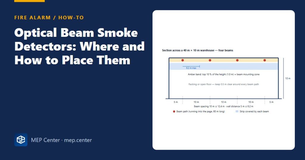
In a warehouse, sports hall or atrium with a 10 m roof, point smoke detectors mean dozens of devices that nobody can reach for testing. Optical beam detectors cover the same space with a handful of units — if you place them correctly. Most beam problems on site (false alarms, faults, blind strips) come from placement, not from the product.
How a beam detector covers a space
A transmitter sends an infrared beam to a receiver (end-to-end type) or to a reflector that returns it (reflective type). Smoke crossing the path obscures the beam, and the detector alarms when the obscuration passes its threshold. Because the beam integrates smoke along its whole length, it suits large open volumes where smoke spreads and dilutes before reaching a point detector.
Placing beams step by step
- Choose the beam direction. Run beams along the longer dimension so you need fewer of them, as long as the path stays within the manufacturer’s maximum (often up to 100 m) and above any minimum length. Why: fewer devices, fewer alignments, fewer faults.
- Set the spacing across the room. Number of beams = room width ÷ 12.4 m, rounded up. Spread them evenly, with the outer beams no more than 6.2 m from the side walls. Why: no point in the room may be outside a covered strip.
- Set the mounting height. Within the top 10 % of the room height, typically 0.3–0.6 m below the roof or ceiling, but not inside a hot, dead air layer at the apex. Why: smoke rises and spreads under the roof first.
- Handle pitched roofs. Put one beam close to the ridge, running along it, then space the others as above. Why: smoke collects at the highest point.
- Keep the path clear. At least 0.5 m between the beam and walls, beams, racking, lights and ducts. Check cranes, high-bay forklifts, hanging banners and stacked goods that may cross the path. Why: a blocked beam is a fault, or worse, a false alarm.
- Fix to rigid structure. Mount transmitters, receivers and reflectors on columns or masonry, not on purlins, sheet cladding or long brackets that move with wind and temperature. Why: a few millimetres of movement at the head is a large miss at 60 m.
- Avoid sunlight and glare. Do not aim the receiver at roof lights, glazed façades or strong lamps. Why: sunlight can saturate the receiver and cause faults.
- Plan access for alignment and testing. Show a mobile platform route or specify a ground-level controller with remote test. Why: beams need periodic realignment and testing at height.
Quick reference
| Check | Typical EN 54-14 practice | NFPA 72 approach |
|---|---|---|
| Lateral coverage | 6.2 m either side of the beam | Per listing and manufacturer instructions |
| Spacing between beams | ≤ 12.4 m | Per listing (half spacing to side walls) |
| Mounting height | Within top 10 % of room height | Near the ceiling per manufacturer; stratification considered |
| Path length | Manufacturer limit, often up to 100 m | Manufacturer limit |
| Clearance | ≥ 0.5 m from walls and obstacles | Unobstructed path per manufacturer |
Typical values — verify with the edition adopted locally.
Tall spaces and stratification
In very tall atria or glazed halls, a warm layer under the roof can stop a cool smoke plume from rising to the beams. The usual answer is an additional level of beams lower down, where the plume is expected, or aspirating detection. Treat this as a design decision you document, not something you discover at commissioning. Ceiling-mounted beams also have a maximum room height in the design code, so check it for spaces above roughly 25 m.
For the point-detector side of the layout, see smoke and heat detector spacing. Beams sit on the loop through interface modules or as loop devices, so include them in your fire alarm loop design; for the rule differences behind the table, read EN 54-14 vs NFPA 72.
Fire Detection and Alarm System Design
Detector selection and layout, loops, panels, voice alarm and real DXF projects to EN 54-14 and NFPA 72.
Modules 1–3 are free, no account needed · full course €8,00 one-time
FAQ
How far apart should beam smoke detectors be?
In EN 54-14 practice each beam covers about 6.2 m either side, so beams are spaced at most 12.4 m apart and the outer beams are no more than 6.2 m from the side walls. Under NFPA 72 follow the listed spacing and the manufacturer’s instructions.
At what height should a beam detector be mounted?
Within the top 10 % of the room height, typically 0.3–0.6 m below the roof or ceiling, on rigid structure. In tall spaces with stratification risk, an extra lower level of beams may be needed.
Reflective or end-to-end beam detector?
Reflective beams need wiring at one end only and are quicker to install; end-to-end beams usually allow longer paths and are less sensitive to reflections from shiny surfaces. Choose by path length, site conditions and access.
More Fire Alarm articles
- Smoke Detector Spacing (and Heat Detectors): Practical Rules
- Conventional vs Addressable Fire Alarm Systems Explained
- Fire Alarm Loop Design: Addresses, Isolators, Zones and Cables
- How to Write a Fire Alarm Cause and Effect Matrix
- Aspirating Smoke Detection: When and How
- Manual Call Point Placement: Distances, Heights, Exits