
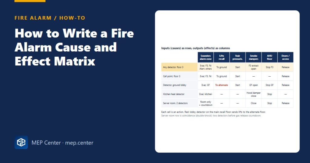
A fire alarm system does not evacuate a building on its own: it stops fans, closes dampers, recalls lifts, releases doors and starts pressurisation fans. The cause and effect matrix is the one document that says exactly which input does what, and it is the document most often argued about at commissioning. Here is how to write one that the mechanical, electrical and architectural teams can all sign.
Step by step
- Start from the fire strategy, not from the panel. Read the evacuation strategy (simultaneous or phased), the smoke control concept, compartments and lift strategy. Why: every output in the matrix must trace back to a decision in the strategy.
- List the inputs (causes) as rows. Group them as the strategy needs: “any automatic detector, floor 3”, “call points, floor 3”, “car park detectors”, “kitchen heat detectors”, “sprinkler flow switch zone 2”, “suppression discharged, server room”, plus supervisory inputs such as valve tamper and fire pump running. Why: rows grouped by zone keep the matrix readable; individual devices only where they act differently.
- List the outputs (effects) as columns. Sounders or voice messages per alarm zone, lift recall, stair pressurisation, smoke dampers, smoke exhaust fans, AHU shutdown, door holder release, access control release, gas shut-off valves, signals to the BMS and the remote monitoring centre. Why: each column becomes one output module or one interface you must wire.
- Fill each cell with an action, not a tick. Write “close”, “stop”, “start”, “recall to ground”, “alert tone”, “evacuate message” — plus any delay. Why: “✓” in the dampers column does not say whether the damper opens (extract) or closes (isolation).
- Define the logic. Single-knock (one device triggers) for most outputs; coincidence or double-knock (two devices) for gas suppression release and other drastic actions; investigation delays only where the authority accepts them. Why: logic is where false alarms and missed actions are born.
- Add the lift rules. Lifts return to the main recall floor; if the fire is detected in the main floor lobby itself, they go to the alternate floor. Why: a lift must never deliver people into the fire floor lobby.
- Separate fire commands from monitoring. Fire actions go through fire alarm output modules; the BMS only receives status via Modbus/BACnet. Why: a BMS fault must never stop a fire action.
- Review and sign. Mechanical (dampers, fans, pressurisation), electrical (lifts, power), architectural (doors, access control) and the fire strategist sign the same revision. Why: one signed revision ends the commissioning arguments.
- Test every non-empty cell. At commissioning, trigger each row and record each output’s response and time. Why: the signed, tested matrix is your proof of performance.
What a good cell looks like
| Weak entry | Better entry |
|---|---|
| ✓ Dampers | Smoke extract dampers floor 3: open. Isolation dampers floor 3: close. |
| ✓ Sounders | Evacuate message floors 3 and 4; alert tone all other floors. |
| ✓ Lifts | Recall to ground; if ground lobby detector, recall to alternate floor (level 1). |
| ✓ Gas suppression | Two detectors in room (coincidence): pre-alarm, close dampers, 30 s countdown, release. |
Common mistakes
- Ticks instead of actions, so nobody knows whether a damper opens or closes.
- Smoke control fans stopped by a general “all HVAC off” command.
- No alternate floor rule for the lift lobby on the recall floor.
- Gas release on a single detector, causing an expensive discharge on a false alarm.
- Fire commands routed through the BMS instead of fire alarm output modules.
- Matrix not updated after a strategy change, so the panel programming and the drawings disagree.
The matrix depends on the zones and alarm zones you set; see fire alarm system types and fire alarm loop design for the output modules each column needs. For server room actions, read clean agent fire suppression for server rooms.
Fire Detection and Alarm System Design
Detector selection and layout, loops, panels, voice alarm and real DXF projects to EN 54-14 and NFPA 72.
Modules 1–3 are free, no account needed · full course €8,00 one-time
FAQ
What is a cause and effect matrix in a fire alarm system?
It is a table that lists every input event as a row and every output as a column, with the required action and any delay in each cell. It defines how the fire alarm panel controls lifts, dampers, fans, doors, sounders and other systems.
Who prepares and signs the cause and effect matrix?
The fire alarm designer usually drafts it from the fire strategy. Mechanical, electrical, architectural and fire strategy teams review it and sign the same revision, and it is tested line by line at commissioning.
What is the NFPA 72 equivalent of a cause and effect matrix?
NFPA 72 calls it the input/output matrix of operation. It is part of the design documents and is used to verify every function during acceptance testing.
More Fire Alarm articles
- Manual Call Point Placement: Distances, Heights, Exits
- Smoke Detector Spacing (and Heat Detectors): Practical Rules
- Optical Beam Smoke Detectors: Where and How to Place Them
- Fire Alarm Loop Design: Addresses, Isolators, Zones and Cables
- Voice Alarm Speaker Spacing and Intelligibility
- Conventional vs Addressable Fire Alarm Systems Explained