
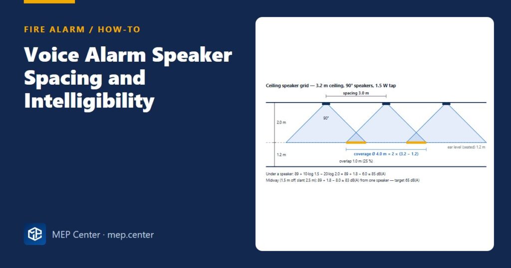
A voice alarm that is loud but unintelligible fails its job: people hear a message, cannot understand it and wait. Most failures at commissioning come from too few, too powerful loudspeakers, not from the equipment rack.
Step by step
- Set the targets for each area. In EN 54 practice: at least 65 dB(A) and 10 dB above ambient noise, below 118 dB(A), and intelligibility STI ≥ 0.50 (CIS ≥ 0.70). Under NFPA 72 the intelligibility target is an average STI ≥ 0.45 (CIS ≥ 0.65) and the level 15 dBA above average ambient. Why: level and intelligibility are separate tests, and both are measured.
- Choose the speaker type by ceiling height and room. Ceiling speakers in suspended ceilings, wall speakers where there is no ceiling, horn/projector or column (line-array) speakers in halls above about 5 m. Why: a ceiling speaker 8 m up spreads its sound over the walls before it reaches the listener.
- Work out the coverage diameter. For a 90° speaker: D ≈ 2 × (H − 1.2 m), with H the ceiling height and 1.2 m the seated ear height. Why: the dispersion angle is quoted where the level has fallen about 6 dB; beyond that circle the listener is off-axis.
- Lay the grid. Spacing = D for edge-to-edge (about ±3 dB uniformity), or 0.7–0.8 × D for 20–30 % overlap, which improves intelligibility. Put speakers along corridors on the centre line and one near each end and turn. Why: overlap fills the gaps where only one speaker is heard at its weakest angle.
- Pick the power tap and check the level. L = S + 10·log10(P) − 20·log10(d), with S the 1 W/1 m sensitivity from manufacturer data (typically 88–92 dB for ceiling speakers), P the tap in W and d the distance in m. Why: the tap is chosen per room; one tap for the whole building wastes amplifier power.
- Treat reverberant rooms differently. Where RT60 is above about 1.5 s (stairs, atria, sports halls, tiled lobbies), use more speakers at lower power, or directional types aimed at the audience. Why: extra power excites more reverberation and lowers STI.
- Match zones to the fire alarm zones and wire A/B. At least one voice alarm zone per storey or fire compartment; speakers alternate between two lines A-B-A-B, radial, in-out, no T-taps, with end-of-line monitoring. Why: a single line fault then costs about 3 dB, not the whole zone.
- Load the amplifier. Add the taps of all speakers on a channel; the total must not exceed 80 % of the amplifier rating, with an N+1 spare amplifier. Why: line loss, ageing and later additions need headroom.
- Measure at commissioning. Level and STI in every zone, with the building in normal use where possible. Why: the calculation predicts; only the measurement proves.
Worked example
Open office 12 m × 9 m, ceiling 3.2 m, ambient 50 dB(A), ceiling speakers 90°, sensitivity 89 dB (1 W/1 m).
Target level: the greater of 65 dB(A) and 50 + 10 = 60 dB(A) → 65 dB(A).
Distance speaker → ear: 3.2 − 1.2 = 2.0 m. Coverage diameter D = 2 × 2.0 = 4.0 m.
Grid: 12 / 3.0 = 4 columns, 9 / 3.0 = 3 rows → 12 speakers at 3.0 m, which is 0.75 × D (25 % overlap).
Level at the 1.5 W tap: under a speaker 89 + 1.8 − 6.0 ≈ 85 dB(A); at the midpoint between two speakers (1.5 m horizontal, slant √(1.5² + 2.0²) = 2.5 m) 89 + 1.8 − 8.0 ≈ 83 dB(A) from one speaker, at 37° off-axis, inside the 45° half-angle. Both are well above 65 dB(A).
Amplifier load: 12 × 1.5 W = 18 W on this zone; add all zones on the channel and keep the total ≤ 80 % of the amplifier rating.
Sanity check: the level margin is large, so the design is governed by coverage and intelligibility, not by power. Keep the 1.5 W tap and spend the budget on coverage, not on power.
Practical spacing guide
| Space | Typical approach |
|---|---|
| Offices, corridors, ceilings about 2.7–3.2 m | Ceiling speakers, spacing from 2 × (H − 1.2 m) with overlap; 4–6 m is common practice in quiet, absorbent areas, verified by measurement |
| Rooms without suspended ceilings | Wall speakers in metal enclosures, aimed along the room |
| Halls, warehouses, atria above about 5 m | Horn/projector or column speakers aimed at the occupied area |
| Reverberant spaces (RT60 above about 1.5 s) | More speakers at lower taps; directional types |
| Plant rooms, noisy production areas | Sounder-beacons where speakers cannot reach 10 dB above ambient |
Typical values — verify with the edition adopted locally.
The zone triggers come from the fire alarm cause and effect matrix, the different sound and intelligibility targets are compared in EN 54 vs NFPA 72 differences, and the voice alarm power supply follows the same method as the fire alarm battery calculation, with the amplifier full-load current for 30 min.
Fire Detection and Alarm System Design
Detector selection and layout, loops, panels, voice alarm and real DXF projects to EN 54-14 and NFPA 72.
Modules 1–3 are free, no account needed · full course €8,00 one-time
FAQ
How far apart should ceiling speakers be for voice alarm?
Start from the coverage diameter at ear level, about 2 × (ceiling height − 1.2 m) for a 90° speaker, and space speakers at that distance or 20–30 % closer for overlap. At a 3.2 m ceiling this gives about 3.0–4.0 m.
What STI is required for a voice alarm system?
In EN 54 practice the target is STI ≥ 0.50 (CIS ≥ 0.70) in every zone, measured at commissioning. NFPA 72 Annex D uses an average STI of at least 0.45 (CIS 0.65).
Why not use fewer, more powerful speakers?
Higher power excites more reverberation and leaves larger off-axis gaps, so intelligibility falls even though the level rises. Many low-power speakers give more even coverage and better STI.
More Fire Alarm articles
- EN 54-14 vs NFPA 72: Fire Alarm Design Differences
- How to Write a Fire Alarm Cause and Effect Matrix
- Optical Beam Smoke Detectors: Where and How to Place Them
- Fire Alarm Standby Battery Calculation
- Fire Alarm Loop Design: Addresses, Isolators, Zones and Cables
- Smoke Detector Spacing (and Heat Detectors): Practical Rules