
A fire alarm panel that runs flat halfway through an evacuation is a design failure, and it usually starts with a battery size copied from the last project. The standby battery calculation takes ten minutes, and it is one of the first things a reviewer checks.
The formula
Ah = 1.25 × [ Is × Ts + Ia × Ta ]
- Is (A) — quiescent current of everything the battery feeds: panel, all loop devices, modules, repeaters, any loop-powered interfaces.
- Ts (h) — standby period on mains failure: 24 h or 72 h (EN 54 practice), 24 h (NFPA 72).
- Ia (A) — current in alarm: panel in alarm plus all sounders, beacons, relay and damper modules that operate, and loop devices with their LEDs on.
- Ta (h) — alarm period at the end of the standby: 0.5 h (EN), 5 min = 0.083 h or 15 min = 0.25 h for voice evacuation (NFPA 72).
- 1.25 — margin for battery ageing and temperature (manufacturers recommend 20–25 %; NFPA projects commonly use 1.2).
Take every current from the manufacturer’s data sheets, per device, in the state it is in during that period. “Typical” currents copied from another brand are the main source of error.
Which durations apply
| Situation | Standby | Then alarm | Margin |
|---|---|---|---|
| EN 54 practice — attended building, or faults transmitted at once to a monitoring centre | 24 h | 30 min | × 1.25 |
| EN 54 practice — not attended, no fault transmission | 72 h | 30 min | × 1.25 |
| NFPA 72 — alarm system | 24 h | 5 min | ≈ 20 % |
| NFPA 72 — emergency voice/alarm communication | 24 h | 15 min | ≈ 20 % |
Typical values — verify with the edition adopted locally.
The 72 h case is the one people miss: a warehouse closed over a long weekend with no remote monitoring triples the standby energy. For the wider rule differences see EN 54 vs NFPA 72 differences.
Worked example
Office building, 2-loop addressable panel, EN 54 practice, attended (24 h + 30 min).
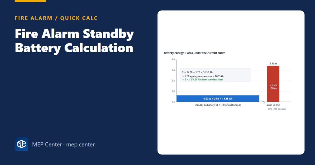
Standby current (from data sheets): panel 0.40 A + loop devices on two loops 0.16 A + one repeater panel 0.06 A = Is = 0.62 A.
Alarm current: panel in alarm 0.55 A + 60 sounders × 25 mA = 1.50 A + 20 beacons × 40 mA = 0.80 A + loop devices 0.16 A + repeater 0.06 A + relay modules 0.33 A = Ia = 3.40 A.
Standby energy: 0.62 × 24 = 14.88 Ah. Alarm energy: 3.40 × 0.5 = 1.70 Ah. Sum 16.58 Ah.
Capacity = 1.25 × 16.58 = 20.7 Ah → two 12 V batteries in series (24 V), next standard size above 20.7 Ah, e.g. 2 × 12 V 24 Ah (or 26 Ah, depending on the range).
Same building, unattended (72 h + 30 min): 1.25 × (0.62 × 72 + 1.70) = 1.25 × 46.34 = 57.9 Ah → 2 × 12 V 65 Ah. That will not fit in most panel cabinets: plan an external EN 54-4 power supply.
Same currents under NFPA 72 (24 h + 5 min, 20 %): 1.2 × (14.88 + 3.40 × 0.083) = 1.2 × 15.16 = 18.2 Ah → just over 18 Ah, so take the next size up.
Sanity check: standby is about 90 % of the energy here. The quiescent current, not the sounders, drives the battery size — so check it device by device.
Rules of thumb that save a redesign
| Item | What to do |
|---|---|
| Rounding | Always up to the next standard size; never “20.7 Ah ≈ 17 Ah plus a bit of margin” |
| Cabinet space | Check the largest battery the panel cabinet takes; above it, an external EN 54-4 power supply supervised by the panel |
| Door holders, magnetic locks | Feed from a separate supervised 24 V supply; they draw current in standby and would dominate the panel battery |
| Voice alarm | Has its own EN 54-4 supply and calculation (amplifier full-load current for 30 min); results are often 2 × 12 V 65–100 Ah |
| Networked panels | One calculation per panel and per power supply, each with its own loads |
| End of discharge | Check sounder circuit voltage drop at the end-of-discharge battery voltage, not at 24 V |
Common slips
- Counting sounders in standby but forgetting loop devices. Two full loops of detectors can draw as much as the panel itself.
- Using the panel’s “alarm current” only. The sounder and beacon load is on top of it.
- Skipping the 1.25 factor because “the battery is new”. It will not be new at the third annual test.
- Not updating after device changes. When the device schedule grows during design, redo the calculation and attach it to the panel schedule.
The loop device counts come straight from your fire alarm loop design, and the relay outputs from the cause and effect matrix. If voice alarm is used, read voice alarm speaker spacing for the amplifier side.
Fire Detection and Alarm System Design
Detector selection and layout, loops, panels, voice alarm and real DXF projects to EN 54-14 and NFPA 72.
Modules 1–3 are free, no account needed · full course €8,00 one-time
FAQ
How do you calculate fire alarm battery size?
Multiply the standby current by the standby time and the alarm current by the alarm time, add the two, and multiply by 1.25 for ageing and temperature. Round up to the next standard battery size.
Is fire alarm standby 24 hours or 72 hours?
In EN 54 practice it is 24 h where the building is attended or faults are transmitted to a monitoring centre, and 72 h where it is not, each followed by 30 min of alarm. NFPA 72 uses 24 h standby followed by 5 min of alarm, or 15 min for voice evacuation.
Do door holders run from the fire alarm battery?
They should not. Door holders and magnetic locks draw current continuously, so feed them from a separate supervised 24 V supply that the fire alarm system releases.
More Fire Alarm articles
- Manual Call Point Placement: Distances, Heights, Exits
- EN 54-14 vs NFPA 72: Fire Alarm Design Differences
- Optical Beam Smoke Detectors: Where and How to Place Them
- How to Write a Fire Alarm Cause and Effect Matrix
- Voice Alarm Speaker Spacing and Intelligibility
- Conventional vs Addressable Fire Alarm Systems Explained