
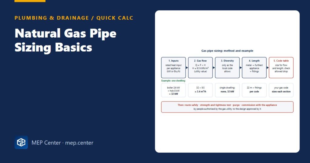
Gas pipework is the one part of a building’s services where “about right” is not good enough. An undersized pipe starves the boiler at full fire and the burner flame lifts or goes out. A badly routed or untested pipe is a safety risk for the whole building. The sizing method is simple. The tables and rules that go with it belong to your local gas code and your gas utility.
The method in five steps
- List the appliances and their heat inputs. Take the rated heat input in kW (or Btu/h) from the appliance data plate or data sheet. Why: the burner draws gas for its input, which is always higher than its useful output.
- Convert to a gas flow. Q = P ÷ H, with Q in m³/h, P in kW and H in kWh/m³. In US units, ft³/h = Btu/h ÷ the heating value in Btu/ft³ (commonly about 1000). Why: pipes are sized for volume flow. Use the calorific value that your utility declares and the same basis (net or gross) as the appliance rating.
- Apply diversity only if your code allows it. Many codes size single dwellings for all appliances at full input, and allow diversity only for groups of dwellings, using their own factors. Why: a boiler and a hob can easily run together, and you cannot assume they won’t.
- Measure the length to the furthest appliance. Include an allowance or the equivalent length for fittings as your code requires. With the “longest length” approach used in US codes, every section is sized using that one total length together with its own flow. Why: the pressure drop builds up along the whole route, so the furthest appliance governs.
- Size from the code’s table or formula and check the pressure drop. Pick the size for each section from the flow and length, then check that the total drop from the meter to each appliance is within the code limit. Why: the appliance needs its minimum inlet pressure at full fire. Low-pressure systems allow only a very small drop.
Appliances: a combination boiler rated at 24 kW heat input and a four-burner hob at 8 kW. Natural gas with a declared net calorific value of 9.5 kWh/m³.
- Total input: 24 + 8 = 32 kW (about 109 000 Btu/h).
- Gas flow: Q = 32 ÷ 9.5 ≈ 3.4 m³/h. In US terms that is 109 000 ÷ 1000 ≈ 109 ft³/h.
- Diversity: none for a single dwelling, so size every section that carries both appliances for 3.4 m³/h, and the hob branch for 8 ÷ 9.5 ≈ 0.84 m³/h.
- Longest length: meter to boiler 22 m, plus the fittings allowance your code requires.
- Read the sizes from your gas code for those flows and that length, and check the total drop against the code limit.
Sanity check: the boiler alone takes 24 ÷ 9.5 ≈ 2.5 m³/h, about three-quarters of the total. That is why the boiler branch, not the hob branch, governs. If the result says the hob branch needs a larger pipe than the boiler branch, recheck the inputs.
Useful reference values
| Item | Typical value |
|---|---|
| Net calorific value, natural gas | about 9.5 kWh/m³ (34 MJ/m³); use the utility’s declared value |
| Heating value used in US practice | about 1000 Btu/ft³ (gross); confirm locally |
| Unit conversion | 1 kW = 3412 Btu/h; 1 m³ = 35.3 ft³ |
| Typical appliance supply pressure, low-pressure systems | about 20 mbar in much of Europe; about 7 in w.c. (17 mbar) in US practice |
| Allowed pressure drop, meter to appliance (low pressure) | very small, for example 1 mbar in UK practice; US code tables are often based on 0.5 in w.c. |
| Typical heat inputs | combination boiler 24–35 kW, domestic hob 6–10 kW, instantaneous water heater 20–30 kW |
Typical values — verify with the edition adopted locally.
Safety points that matter more than the size
- Routing: keep gas pipes out of lift shafts, air ducts, chimneys and flues, electrical rooms and unventilated voids. Where they must pass through a building element, use a sleeve and seal it, and keep the clearances to electrical services that the code requires.
- Isolation: fit an emergency control valve at the meter, an isolation valve before each appliance, and in commercial kitchens and plant rooms an automatic shut-off valve linked to gas detection and the fire alarm.
- Ventilation and combustion air: the appliance room needs the air supply and flue arrangement the code sets for the appliance type. Gas pipe sizing does not cover this, but no installation passes without it.
- Joints and materials: use only the materials and jointing methods the code and utility accept. Do not put mechanical joints in concealed or inaccessible positions, and protect steel against corrosion.
- Bonding: bond the gas installation pipework to the main earthing terminal as the electrical rules require; see earthing systems explained.
- Testing and purging: strength and tightness tests at the pressures and durations the code sets, then purging, then appliance commissioning, all recorded.
- Approvals: in most countries the gas utility approves the design and only authorised firms may install, test and connect.
Gas boilers feed systems sized elsewhere: see hydronic heating pipe sizing and hot water storage cylinder sizing. Commercial kitchens add an exhaust hood calculation; see kitchen hood exhaust airflow.
Ready-made drawings and tools for your next project
CAD block libraries, detail drawings and AutoCAD tools made by practising MEP engineers.
FAQ
How do I calculate the gas flow for an appliance?
Divide its rated heat input by the calorific value of the gas: Q = P ÷ H. A 24 kW boiler on natural gas at about 9.5 kWh/m³ needs about 2.5 m³/h. Use the value your utility declares, on the same net or gross basis as the appliance rating.
Why does this article not give a gas pipe sizing table?
Because the allowed pressure drop, the gas supply pressure, the fittings allowance and the accepted materials all differ between codes and utilities. Use the tables or formula in the gas code adopted where the building is, and have the design approved by the utility.
Should I use the appliance input or output for gas pipe sizing?
Always the rated heat input. The burner draws gas for its input, which is higher than the useful heat output by the appliance’s losses.