
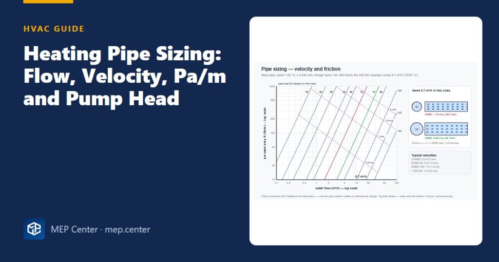
A perfectly chosen boiler or heat pump with perfectly sized radiators still gives cold rooms, noisy valves and high pump bills if the water does not arrive where it should. Heating pipe sizing is the strongest lever you have on pump energy: one pipe size can change the friction loss by a factor of four. This guide shows you how to go from kW to flow, pick the pipe by velocity and pressure drop, and turn the index circuit into a pump duty – with worked numbers you can check.
- Flow first: V̇ (m³/h) ≈ 0.86 × Φ (kW) / Δθ (K). The design temperature difference decides pipe and pump sizes.
- Apply two criteria together: a velocity limit (noise, erosion) and a pressure drop of about 100–200 Pa/m (pump energy).
- Use Darcy–Weisbach with the viscosity at the water temperature. Hazen–Williams is for cold water and fire protection, not heating.
- The pump head equals the pressure drop of the index circuit – pipes, fittings, heat source, control valve and terminal – not the building height.
- Heat pumps at 5 K need four times the flow of boilers at 20 K: size pipes, valves and pumps for it.
- Balancing is part of the design: every terminal needs its design flow, and no more.
Step 1 – From heat load to water flow
V̇ (m³/h) ≈ 0.86 × Φ (kW) / Δθ (K) or q (L/h) = 860 × Φ (kW) / Δθ
Φ is the heat load the pipe carries and Δθ the difference between flow and return temperature. The load comes from the room heat loss – if you have not done it yet, start with our heat loss calculation guide.
| Load | Δθ = 20 K | Δθ = 10 K | Δθ = 5 K |
|---|---|---|---|
| 10 kW | 0.43 m³/h | 0.86 m³/h | 1.72 m³/h |
| 100 kW | 4.3 m³/h | 8.6 m³/h | 17.2 m³/h |
| 500 kW | 21.5 m³/h | 43 m³/h | 86 m³/h |
Typical spreads: 20 K for boiler systems at 70/50 °C, 10 K for radiators at 55/45 °C, 5 K for many heat pump circuits. Lower flow temperatures also mean bigger emitters and more water: the 904 W living room from our heat loss example needs 78 L/h at 55/45 °C, but 155 L/h at 45/40 °C.
Step 2 – Velocity limits
| Pipe size | Typical maximum velocity |
|---|---|
| ≤ DN15–20 (dwellings, branches to emitters) | 0.3–0.5 m/s |
| DN25–DN50 | 0.5–1.0 m/s |
| DN65–DN150 | 1.0–1.5 m/s |
| > DN150 (plant rooms, district heating) | 1.5–3.0 m/s |
Above these, expect flow noise, erosion at fittings and air carried round the system. Far below them, pipes get expensive and air is not swept to the separators.
Velocities, friction rates, ζ values and pipe dimensions in this guide are typical – verify with the edition adopted locally, the national guide and the manufacturer’s data for your pipe.
Step 3 – Pressure drop per metre
The economic criterion is the friction rate R: typically 100–200 Pa/m for building distribution, up to 250–300 Pa/m in plant rooms and short mains, and 50–100 Pa/m for long mains running many hours a year. Friction is calculated with Darcy–Weisbach:
R = λ / d × ρ v² / 2 (Pa/m)
λ = friction factor, d = internal diameter (m), ρ = water density (kg/m³), v = velocity (m/s). λ comes from the Colebrook equation or its explicit Swamee–Jain form, λ = 0.25 / [log10(ε / 3.7d + 5.74 / Re0.9)]², with Re = v d / ν. Use roughness ε ≈ 0.045 mm for steel and 0.0015–0.007 mm for copper, plastics and multilayer. Viscosity ν changes a lot with temperature: about 1.31 × 10⁻⁶ m²/s at 10 °C, 0.66 × 10⁻⁶ at 40 °C, 0.475 × 10⁻⁶ at 60 °C and 0.365 × 10⁻⁶ at 80 °C. That temperature dependence is exactly why Hazen–Williams, which ignores it, is not used for heating water.
Internal diameters of medium-series steel pipe (check the actual pipe standard on your project):
| DN | 15 | 20 | 25 | 32 | 40 | 50 | 65 | 80 | 100 |
|---|---|---|---|---|---|---|---|---|---|
| ID (mm) | 16.1 | 21.7 | 27.3 | 36.0 | 41.9 | 53.1 | 68.9 | 80.9 | 105.3 |
| Flow at 1 m/s (m³/h) | 0.73 | 1.33 | 2.11 | 3.66 | 4.96 | 7.97 | 13.4 | 18.5 | 31.4 |
Worked example – sizing a 200 kW heating main
Inputs
- Heating main, 200 kW at 70/50 °C (Δθ = 20 K)
- Water at about 60 °C: ρ = 983 kg/m³, ν = 0.475 × 10⁻⁶ m²/s
- Steel pipe, ε = 0.045 mm; design limit R ≤ 200 Pa/m
Step 1 – Flow
ṁ = 200 / (4.19 × 20) = 2.387 kg/s → V̇ = 2.387 / 983 = 0.00243 m³/s ≈ 8.7 m³/h. (Quick rule: 0.86 × 200 / 20 = 8.6 m³/h ✓.)
Step 2 – Try DN50 (d = 53.1 mm, A = 2.214 × 10⁻³ m²)
v = 0.00243 / 0.002214 = 1.10 m/s; Re = 1.10 × 0.0531 / 0.475 × 10⁻⁶ ≈ 123 000
λ = 0.25 / [log10(0.000229 + 0.000150)]² = 0.25 / 11.70 = 0.0214
R = 0.0214 / 0.0531 × 983 × 1.10² / 2 ≈ 240 Pa/m ✗ (above 200 Pa/m, and 1.10 m/s is above the DN25–50 range)
Step 3 – Try DN65 (d = 68.9 mm, A = 3.728 × 10⁻³ m²)
v = 0.00243 / 0.003728 = 0.65 m/s; Re ≈ 94 300
λ = 0.25 / [log10(0.000177 + 0.000191)]² = 0.25 / 11.79 = 0.0212
R = 0.0212 / 0.0689 × 983 × 0.65² / 2 ≈ 64 Pa/m ✓
Result
DN65: 0.65 m/s and 64 Pa/m. One size up cut the friction by a factor of almost four – R falls roughly with d−5 at constant flow.
Sanity check
From the table, DN65 carries 13.4 m³/h at 1 m/s, so 8.7 m³/h gives 8.7 / 13.4 = 0.65 m/s ✓. And R scales with about v² / d: 240 × (0.65 / 1.10)² × (53.1 / 68.9) ≈ 65 Pa/m, close to the 64 Pa/m calculated ✓.
A small-system check: the whole house
The same method works at house scale. The house from our heat loss guide needs about 4.28 kW at 55/45 °C: 0.86 × 4.28 / 10 ≈ 0.37 m³/h (370 L/h). In steel DN15 that is 0.51 m/s and roughly 260 Pa/m – too much. DN20 gives about 0.28 m/s and 60 Pa/m, so DN20 is the right size for the boiler or heat pump connection. Copper, PE-X and multilayer pipes have different internal diameters and lower roughness, so use the manufacturer’s tables for them.
Fittings, valves and equipment
Local losses are Δp = ζ × ρ v² / 2. Typical ζ: smooth bend 0.3–0.5, pressed or threaded elbow 0.7–1.5, tee into a branch 1.0–1.5, tee straight through 0.2–0.5, open ball valve 0.1–0.3, clean strainer 2–5. Valves are given by Kv (m³/h at 1 bar): Δp (bar) = (V̇ / Kv)². Boilers, heat exchangers, coils and heat meters come with a pressure drop at design flow on their data sheets.
For early design, add 30–50 % to the straight-pipe friction for fittings, then replace it with a fitting-by-fitting calculation for the final design. The same “index run” logic applies on the air side – see the duct sizing guide.
From pipe sizes to pump head
In a closed circuit the pump does not lift water – the return column balances the static height. It only overcomes friction along the index circuit: the path from the pump through the most resistant terminal and back, usually but not always the most distant one.
| Index circuit of the 200 kW system | Δp (kPa) |
|---|---|
| Pipes, flow and return, 120 m at an average 150 Pa/m | 18.0 |
| Fittings (50 % of pipe friction) | 9.0 |
| Heat source (boiler heat exchanger or header connection) | 10.0 |
| Two-way control valve at the index terminal | 10.0 |
| Terminal (coil or radiator with valve presetting) | 8.0 |
| Strainer, isolating valves, heat meter | 2.0 |
| Pump head | 57 kPa ≈ 5.8 m |
Pump duty: 8.7 m³/h at 57 kPa. Hydraulic power = 0.00243 m³/s × 57 000 Pa ≈ 138 W; at about 50 % overall pump efficiency that is roughly 275 W electrical. A three-speed pump picked “one size up” could easily draw twice that for 5 000 hours a year. The system curve rises with the square of flow (here Δp = 0.753 × V̇² kPa with V̇ in m³/h), and speed control pays: at 70 % speed a pump gives 70 % flow, 49 % head and only about 34 % of the power. Use proportional-pressure (Δp-v) control for radiator systems with significant pipe losses, or a remote Δp sensor at the index circuit for large systems.
Balancing – the last step of pipe sizing
Terminals near the pump see a high differential pressure, far ones a low one. Without balancing the near ones overflow and the far rooms are cold on cold mornings. Size the valves and presettings with the same Kv relation. Example: a riser with a differential pressure controller holds 10 kPa; a radiator needing 78 L/h with 1 kPa of pipe loss has 9 kPa for its valve, so Kv = 0.078 / √0.090 = 0.26. Without the controller that radiator might see 40 kPa when other valves close, pushing 0.26 × √0.40 = 0.164 m³/h – 164 L/h, twice its design flow, and the valve whistles. For fan coils and AHU coils, pressure-independent control valves (PICVs, typically needing 15–30 kPa minimum) do the balancing automatically.
Common mistakes
- Sizing long mains by velocity only (high R and pump energy), or branches by R only (noise).
- Using Hazen–Williams or cold-water tables for hot water.
- Keeping 20 K pipe sizes when the system is converted to a heat pump at 5–10 K.
- Guessing the pump head, or selecting from the largest pump in the catalogue and running it on top speed.
- Constant-speed pumps on variable-flow systems with two-way valves.
- Oversized control valves – low authority and hunting.
- No balancing devices, or static balancing only in a variable-flow system.
- Three-way bypass valves at every terminal in condensing boiler, heat pump or district heating systems – they raise the return temperature.
Quick checklist
- Design flow and return temperatures per circuit; flows calculated with 0.86 × Φ / Δθ.
- Pipes checked for both velocity and Pa/m, with viscosity at the operating temperature.
- Index circuit identified; pump head built up component by component.
- Pump control mode and set point stated; duty/standby where critical.
- Control valves selected by Kv with authority ≥ 0.5, or PICVs.
- Balancing strategy and presettings in the valve schedule.
- Pipe sizes, flow directions, vents, drains and expansion points on the drawings.
HVAC Systems Design — Heating, Cooling & Ventilation
28 modules from heat loss to plant room: boilers, heat pumps, cooling loads, psychrometrics, AHUs and ductwork. The VRF course is included.
Modules 1–3 are free, no account needed · full course €15,00 one-time
FAQ
What velocity should water have in heating pipes?
Typically 0.3–0.5 m/s up to DN20, 0.5–1.0 m/s for DN25–DN50, 1.0–1.5 m/s for DN65–DN150 and 1.5–3.0 m/s above DN150. Check the pressure drop per metre as well.
What pressure drop per metre is normal for heating pipes?
About 100–200 Pa/m for building distribution, up to 250–300 Pa/m in plant rooms and short mains, and 50–100 Pa/m for long mains with many operating hours.
How do I calculate the flow rate for a heating circuit?
Use V̇ (m³/h) ≈ 0.86 × Φ (kW) / Δθ (K). For example, 200 kW at a 20 K spread needs about 8.6–8.7 m³/h, and the same load at 5 K needs four times as much.
Can I use Hazen–Williams for heating pipes?
No. Hazen–Williams ignores the strong effect of water temperature on viscosity, so use Darcy–Weisbach with a friction factor from Colebrook or Swamee–Jain.
How do I find the pump head for a heating system?
Add up the pressure drops along the index circuit: pipes, fittings, heat source, control valve, terminal and accessories. Building height does not count in a closed system; in the worked example the head is 57 kPa.