
Picking an MCB looks trivial — “16 A for sockets, 10 A for lights” — until a reviewer asks why the whole floor goes dark when one kettle fails, or why a long circuit will not trip within 0.4 s. A correct MCB matches the load, protects the cable, clears earth faults in time, survives the fault level, and ideally trips alone.
This guide walks through those five checks in the order you do them, explains what discrimination (selectivity) between MCBs can and cannot achieve, and works one circuit through from load to selectivity limit.
- Rating: Ib ≤ In ≤ Iz — the MCB sits between the load current and the corrected cable capacity.
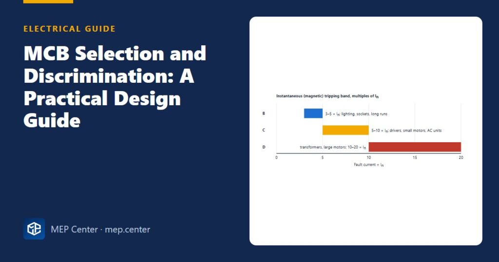
- Curve: B trips magnetically at 3–5 × In, C at 5–10 × In, D at 10–20 × In. Use the lowest curve the inrush allows.
- Earth faults: the fault-loop impedance must let at least the upper magnetic threshold flow (5 × In for B, 10 × In for C).
- Breaking capacity must be at least the prospective fault current at the board (typically 6 kA or 10 kA MCBs).
- MCB-to-MCB discrimination is usually only partial: it holds up to roughly the upstream device’s lower magnetic threshold.
- For full selectivity, use manufacturer selectivity tables, and an MCCB or fuse upstream where the fault level demands it.
Check 1 — the rating
Start from the design current Ib of the circuit (A) and pick the next standard rating In at or above it. Common MCB ratings are 6, 10, 13, 16, 20, 25, 32, 40, 50 and 63 A. Then confirm that the cable’s corrected current-carrying capacity Iz (A) is at least In.
The overload rule I2 ≤ 1.45 × Iz (I2 = current that surely trips the device in conventional time) is automatically met by MCBs to IEC 60898-1, because their I2 is 1.45 × In. So for MCBs, In ≤ Iz is the whole overload check. Cable capacity and grouping factors are covered in our guide to cable sizing and voltage drop.
Check 2 — the tripping curve
Every MCB has a thermal part (slow, for overloads) and a magnetic part (instant, for short circuits and earth faults). The curve letter tells you where the magnetic part starts.
| Curve | Magnetic trip | Use for | Watch out |
|---|---|---|---|
| B | 3–5 × In | Resistive loads, domestic sockets and lighting, long final circuits | Nuisance trips on large LED groups and motors |
| C | 5–10 × In | Commercial lighting with drivers, small motors, split units, IT loads | Needs half the loop impedance of B for the same rating |
| D | 10–20 × In | Transformers, welding sets, motors with heavy starting | Very low Zs required; often impossible on long runs |
Use the lowest curve that does not nuisance-trip. A higher curve does not “protect better” — it makes the earth-fault check harder, because more current is needed to trip it instantly. Many LED drivers have inrush peaks well above their running current; manufacturer data gives the maximum number of drivers per B16 or C16 MCB.
Trip bands, Zs limits, breaking capacities and selectivity limits in this article are typical — verify with the edition adopted locally and with manufacturer data, especially selectivity tables.
Check 3 — earth-fault disconnection
On TN systems the MCB must clear an earth fault within the required time (typically 0.4 s for final circuits up to 32 A at 230 V). It does so only if the fault current reaches its upper magnetic threshold Ia:
Zs ≤ 0.95 × U0 / Ia
Zs is the earth-fault loop impedance at the far end of the circuit (Ω), U0 the line-to-earth voltage (230 V), 0.95 an allowance for supply voltage tolerance, and Ia = 5 × In (type B) or 10 × In (type C). For a B16 this gives 2.73 Ω; for a C16, 1.37 Ω. On TT systems the fault current is far too small for any MCB, and RCDs do the job — see TN-S vs TN-C-S vs TT earthing.
Check 4 — breaking capacity
The MCB must interrupt the highest fault current that can flow at its location. IEC 60898-1 MCBs are typically rated 4.5, 6 or 10 kA (Icn). Calculate the prospective short-circuit current at each board — it falls quickly with distance from the transformer — and choose:
- 6 kA MCBs for most sub-boards in commercial buildings and homes.
- 10 kA MCBs (or higher-rated devices to IEC 60947-2) close to large transformers.
- Where the fault level exceeds the MCB rating, back-up (cascading) protection by an upstream device is possible, but only with combinations confirmed in manufacturer tables.
Check 5 — discrimination (selectivity)
Discrimination means that only the device directly upstream of a fault trips. Between two MCBs it works in two zones:
- Overload zone: selective when the upstream rating is clearly larger — a ratio of at least 2 is a common rule of thumb (for example 32 A over 16 A).
- Short-circuit zone: selective only while the fault current stays below the upstream MCB’s lower magnetic threshold. Above that, both trip instantly and you lose the whole board.
So for MCBs, the selectivity limit is roughly the lower edge of the upstream device’s magnetic band (5 × In for an upstream type C). Manufacturer tables often show a somewhat higher value, because a small downstream MCB limits the let-through current; never assume more than the tables say.
For total selectivity on important circuits, the usual answers are an upstream MCCB with an adjustable or time-delayed instantaneous setting, a fuse with enough I²t margin, or a selective main MCB designed for this purpose — all chosen from manufacturer selectivity tables.
Worked example: a socket circuit under a 63 A sub-main
Inputs
- TN-C-S supply; sub-board fed from the main board through a 63 A type C MCB and 25 mm² cable (65 m).
- Earth-fault loop impedance at the sub-board Zdb = 0.50 Ω (Ze 0.35 Ω + sub-main 0.15 Ω). Prospective short-circuit current at the sub-board ≈ 1 kA.
- Final circuit: socket radial, Ib = 14 A, 30 m, 2.5 mm² line + 1.5 mm² protective conductor, clipped direct, bunched with two other circuits.
Step 1 — rating
Ib = 14 A → In = 16 A.
Iz = 27 A (2.5 mm², method C) × 0.70 (3 circuits grouped) = 18.9 A ≥ 16 A ✓.
Step 2 — curve
Resistive and small appliance loads, no large inrush → type B16.
Step 3 — earth fault
R1 + R2 = (7.41 + 12.10) mΩ/m × 30 m × 1.20 = 0.70 Ω.
Zs = 0.50 + 0.70 = 1.20 Ω. Limit for B16: 0.95 × 230 / (5 × 16) = 218.5 / 80 = 2.73 Ω ✓.
Fault current at the far end: If = 230 / 1.20 ≈ 192 A ≥ 80 A ✓.
Step 4 — breaking capacity
≈ 1 kA at the board → a 6 kA MCB has ample margin ✓.
Step 5 — selectivity with the C63 upstream
Overload: 63 / 16 ≈ 3.9 ≥ 2 ✓.
Short circuit: C63 lower magnetic threshold = 5 × 63 = 315 A → selectivity limit ≈ 315 A.
Fault at the far end (F2): 192 A < 315 A → only the B16 trips ✓.
Fault at the board’s outgoing terminals (F1): If ≈ 230 / 0.50 = 460 A > 315 A → the C63 may trip too ✗ (partial selectivity).
Result — B16, 6 kA, on 2.5/1.5 mm²: rating, curve, disconnection and breaking capacity all pass. Selectivity holds for faults along most of the circuit but not for faults close to the sub-board. If the whole board must stay on for any final-circuit fault, replace the C63 with an MCCB whose instantaneous setting and selectivity table cover at least 460 A.
Sanity check — the circuit could be longer before the earth-fault check fails: (2.73 − 0.50) / (19.51 × 1.20 / 1000) = 2.23 / 0.0234 ≈ 95 m. The selectivity point where the fault current falls to 315 A is Z = 230 / 315 = 0.73 Ω, i.e. (0.73 − 0.50) / 0.0234 ≈ 10 m from the board. Faults in the first 10 m of the cable are the ones that can trip the C63.
RCDs and RCBOs in the same scheme
Sockets for general use and many outdoor and bathroom circuits need 30 mA additional protection. An RCBO (MCB + RCD in one) per circuit gives the best selectivity, because an earth leakage on one circuit trips only that circuit. If you use an upstream RCD for a group, keep groups small. Between RCDs in series, selectivity needs a time-delayed (type S) upstream device and a ratio of rated residual currents of at least 3 (for example 100 mA S over 30 mA).
Splitting circuits to reduce nuisance tripping often changes phase loads too; re-check the board with phase balancing in panel schedules.
Common mistakes
- Choosing the MCB from the cable size alone, without checking Ib — or the cable from the MCB without grouping factors.
- Using type C “to be safe” on long final circuits, which halves the allowed Zs and fails the disconnection check.
- Ignoring the fault level: a 6 kA MCB at a main board with 15 kA prospective current and no confirmed back-up.
- Claiming full selectivity between two MCBs without a manufacturer table.
- Putting a whole floor’s sockets behind one 30 mA RCD, so one leaky appliance blacks out everything.
- Forgetting LED driver inrush, then swapping to a higher curve on site without re-checking Zs.
Quick checklist
- Ib ≤ In ≤ Iz (corrected) for every circuit.
- Lowest curve that handles the inrush; curve shown on the schedule.
- Zs ≤ Zs,max at the far end of every TN circuit; RCDs on TT.
- Breaking capacity ≥ prospective fault current at each board, or back-up confirmed.
- Selectivity limit stated for critical boards and backed by manufacturer tables.
- RCD/RCBO arrangement and ratings shown on the single-line diagram.
Electrical Power Systems Design for Buildings
35 modules from the MV connection to the socket: transformers, short circuit, protection and selectivity, cable sizing, boards, generators, earthing, surge and lightning protection. Includes 50 % off TEKHAT.
Modules 1–3 are free, no account needed · full course €15,00 one-time
FAQ
What is the difference between B, C and D curve MCBs?
They trip instantly at different multiples of their rated current: type B at 3 to 5 times, type C at 5 to 10 times and type D at 10 to 20 times. Use the lowest curve that does not trip on the load’s inrush current.
How do I choose the MCB rating for a circuit?
Pick the next standard rating at or above the design current, then check that the cable’s corrected current-carrying capacity is at least that rating. Then confirm the earth-fault loop impedance and the breaking capacity.
Can two MCBs in series be fully selective?
Usually not. Selectivity between MCBs normally holds only up to about the upstream device’s lower magnetic threshold, for example about 315 A for a C63. For full selectivity use manufacturer selectivity tables and an MCCB or fuse upstream where needed.
What breaking capacity should an MCB have?
At least the prospective short-circuit current at the board where it is installed. 6 kA is common for sub-boards and homes, 10 kA or higher near large transformers, unless a back-up combination is confirmed by the manufacturer.
What is the maximum earth loop impedance for a B16 MCB?
Using 230 V, a 0.95 voltage factor and the type B upper threshold of 5 times 16 A, the limit is about 2.73 ohms for 0.4 s disconnection. Check the value given in the edition adopted locally.
TEKHAT – Single-Line Diagram & Load Schedule
Draw panel single-line diagrams and load schedules in minutes, with breaker, RCD and cable sizing. Buyers of the Electrical Power Systems Design course get 50 % off.
Free install from the Microsoft Store · 30-day trial · licence 20 € for all your devices or €15 per computer on our site