
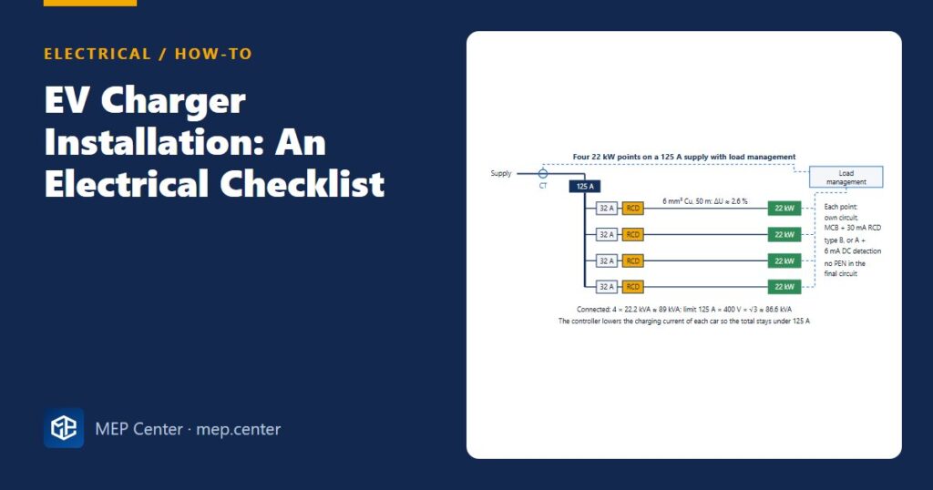
An EV charger looks like a socket on a post, but electrically it is closer to a heater that runs flat out for hours. Add DC leakage from the vehicle and an outdoor location on a TN-C-S supply, and the usual “radial with a 30 mA RCD” can be both overloaded and unsafe. Use this checklist from the first load estimate to commissioning.
The checklist
- Check the supply capacity first. List the existing maximum demand, then add the chargers at full current. Why: a charger has no diversity on its own, and a car can draw full current for 4–8 hours.
- Choose power and mode. Typical AC Mode 3 points are 7.4 kW (32 A single phase), 11 kW (16 A three phase) and 22 kW (32 A three phase). DC Mode 4 chargers are 50–350 kW. Why: most cars charge on AC at 7.4–11 kW, so 22 kW everywhere often buys capacity nobody uses.
- Use load management for groups. A controller reads the incomer current and shares a fixed limit between points. For example, 125 A at 400 V ≈ 86.6 kW for all chargers together. Why: it avoids a supply upgrade, and cars rarely all need full power at once.
- Give each point a dedicated final circuit with its own MCB or RCBO. Why: a fault on one charger must not disconnect the others, and each circuit carries continuous full load.
- Use the right RCD type. 30 mA per connection point: type B, or type A/F plus an RDC-DD (6 mA DC detection). Check the charger data: many include the 6 mA DC detection. Never put a type B circuit downstream of a type A RCD. Why: smooth DC leakage from the vehicle blinds a type A device.
- Get the earthing right. No PEN in the final circuit. For outdoor points on TN-C-S, use an open-PEN protection device (often built into the charger) or a local TT electrode, as national rules allow. Why: a broken PEN can put the car body at a dangerous voltage while someone touches it from the ground.
- Size the cable for continuous duty. Iz ≥ In with grouping and burial factors, and voltage drop within limits. Under NEC 625 the circuit is rated at 125 % of the charger current. Why: cables that are fine for intermittent loads overheat at hours of full current.
- Location and mounting. Use outdoor-rated equipment (typically IP54 or better, IK08 where vehicles or the public can hit it), bollards or wheel stops, and keep the connector or socket at an easy height (typically 0.5–1.5 m). Keep cable routes away from parking manoeuvres. Why: impact damage is the most common failure.
- Surge protection and data. Fit an SPD where the risk assessment calls for one, especially on long outdoor runs. Provide a network or SIM connection for billing and load management. Why: charger electronics are sensitive, and smart functions need a reliable connection.
- Test and commission. Insulation resistance, continuity, loop impedance, RCD trip tests (and the DC detection function as the maker describes), a charging test with a vehicle simulator or test adapter, and a load management test with several points active. Why: most handover problems show up only when two or more cars charge at once.
Worked example: cable for a 22 kW point
6 mm²: R = 0.0225 × 50 / 6 = 0.1875 Ω → ΔU = √3 × 32 × 0.1875 = 10.4 V = 2.6 %.
4 mm²: R = 0.281 Ω → ΔU = 15.6 V = 3.9 %; with the drop upstream this is usually too much.
Result: 6 mm² Cu, provided its rating after grouping and installation factors is ≥ 32 A. Check disconnection time at the far end with the loop impedance.

Common slips
- Applying normal socket diversity to chargers. Without load management, take them at full current.
- Chargers fed from a board protected by an upstream type A RCD. DC leakage can blind it. See RCD types AC, A, F and B.
- A local TT electrode for the charger placed too close to the building’s earth, or never tested. See how to measure earth electrode resistance and earthing systems explained.
- No space left on the board for future points. Add spare ways and leave the containment oversized.
Typical values — verify with the edition adopted locally. Open-PEN and RCD rules for EV charging vary by country.
Electrical Power Systems Design for Buildings
35 modules from the MV connection to the socket: transformers, short circuit, protection and selectivity, cable sizing, boards, generators, earthing, surge and lightning protection. Includes 50 % off TEKHAT.
Modules 1–3 are free, no account needed · full course €15,00 one-time
FAQ
What RCD does an EV charger need?
Each connection point needs a 30 mA RCD. It must be type B, or type A or F combined with a 6 mA DC fault detection device, which many chargers have built in. A type B circuit must not be installed downstream of a type A RCD.
What cable size do I need for a 22 kW EV charger?
A 22 kW charger draws 32 A on three phases. For a run of around 50 m, 6 mm² copper gives about 2.6 % voltage drop. Always check the rating after installation factors and the loop impedance for your own route.
Can I install several chargers without upgrading the supply?
Often yes, with load management. A controller measures the incomer current and shares a fixed limit, for example 125 A, between the cars that are charging. Without it, each charger must be counted at full current.
TEKHAT – Single-Line Diagram & Load Schedule
Draw panel single-line diagrams and load schedules in minutes, with breaker, RCD and cable sizing. Buyers of the Electrical Power Systems Design course get 50 % off.
Free install from the Microsoft Store · 30-day trial · licence 20 € for all your devices or €15 per computer on our site
More Electrical articles
- IEC vs NEC: Earthing, Grounding and Bonding Terms Compared
- MCB Selection and Discrimination: A Practical Design Guide
- Lightning Protection Basics: Rolling Sphere and Mesh Method
- TN-S vs TN-C-S vs TT Earthing: Systems Explained (Plus IT)
- Cable Gland Selection: Size, Armour, IP and Earthing
- IP Ratings Explained: Choosing IP44, IP54, IP65 on Site