
An earth electrode reading of “42 Ω” means nothing unless you know where the probes were and whether the reading was stable. The fall-of-potential method gives a credible number in about twenty minutes, if you follow the steps and do the plateau check.
How the method works
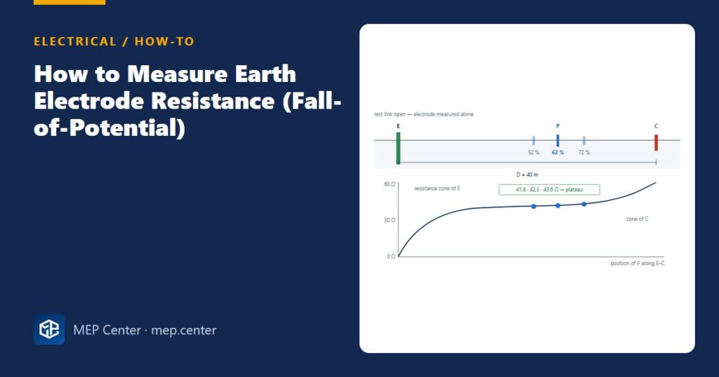
The tester drives a current between the electrode E and the current probe C, and measures the voltage between E and the potential probe P. Each electrode is surrounded by a zone of soil where most of its resistance lies. P has to sit in the “neutral” ground between the zones of E and C. For a simple hemispherical model, that point is at 62 % of the E–C distance. If the zones overlap, there is no flat region and every reading is wrong.
Step by step
- Isolate safely and open the test link between the electrode and the installation (or the LPS test joint). Why: otherwise you measure the whole bonded network of pipes, cable sheaths and neighbouring earths, not the electrode.
- Pick a line for the probes away from buried metal pipes, cables and fences, and ideally at right angles to them. Why: buried metal distorts the voltage gradient.
- Set D. Use at least 5–10 × the largest dimension of the electrode: for a 3 m rod, 30–40 m is comfortable. A ring or mesh needs far more. Why: too short a D makes the two resistance zones overlap.
- Drive C at D and P at 0.62 × D on the straight line E–C, with good soil contact (wet the soil if it is very dry). Why: 62 % is the point where the reading equals the true resistance for a hemispherical model.
- Connect the leads E, P and C (on a 4-terminal tester, link the E and ES leads at the electrode). Check the instrument’s probe-resistance warnings. Why: high probe resistance or noise makes the reading meaningless.
- Read, then move P to 52 % and 72 % of D (±10 % of D). Why: this is the plateau check. One reading alone proves nothing.
- Accept or repeat. If the readings are within about 5 % of the 62 % value, record it. If not, increase D and repeat. Why: a rising curve means the zones still overlap.
- Record the conditions: date, weather, soil state, instrument, D and the three readings. Close the test link. Why: a value measured after a week of rain will be higher in a dry month.
Spread: −1.6 % / +2.6 % around 42.5 Ω → within 5 % → RA = 42.5 Ω.
TT check: RA × IΔn ≤ 50 V → with a 30 mA RCD: 42.5 × 0.03 = 1.3 V ✓; with a 100 mA device: 4.25 V ✓.
If the readings had been 30, 42 and 60 Ω, there would be no plateau. Move C further away and repeat the test.
Typical targets
| Electrode | Typical target |
|---|---|
| TT installation | RA × IΔn ≤ 50 V; in practice aim ≤ 100–200 Ω for stability |
| Lightning protection earth termination | Low value, ≤ 10 Ω where possible |
| Substation combined earth (TN) | ≤ 1–2 Ω, or as set by a touch/step voltage study |
| NEC single rod | ≤ 25 Ω, otherwise a supplemental electrode |
Typical values — verify with the edition adopted locally.
When you cannot lay out 40 m
A clamp-on (stakeless) tester reads an electrode without probes. It only works where the electrode is part of a parallel network, and it measures the whole loop, not the electrode alone. Use it for periodic checks of multi-electrode systems, not for proving a single TT electrode. To understand what the number means for your protective devices, read TN, TT and IT earthing explained. For the terminology differences with US practice, see IEC vs NEC earthing and grounding terms.
Electrical Power Systems Design for Buildings
35 modules from the MV connection to the socket: transformers, short circuit, protection and selectivity, cable sizing, boards, generators, earthing, surge and lightning protection. Includes 50 % off TEKHAT.
Modules 1–3 are free, no account needed · full course €15,00 one-time
FAQ
Why is the potential probe placed at 62 %?
For a hemispherical electrode in uniform soil, the potential at 62 % of the distance to the current probe gives a reading equal to the true electrode resistance. The ±10 % plateau check confirms that the model holds on your site.
How far away should the current probe be?
At least 5–10 times the largest dimension of the electrode under test. For a single 3 m rod, 30–40 m is typical. Rings, meshes and foundation electrodes need considerably longer distances.
Do I need to disconnect the earth electrode before testing?
Yes, for the fall-of-potential method. Isolate safely and open the test link, otherwise the reading includes all the bonded services in parallel. Close the link again after the test.
TEKHAT – Single-Line Diagram & Load Schedule
Draw panel single-line diagrams and load schedules in minutes, with breaker, RCD and cable sizing. Buyers of the Electrical Power Systems Design course get 50 % off.
Free install from the Microsoft Store · 30-day trial · licence 20 € for all your devices or €15 per computer on our site
More Electrical articles
- TN-S vs TN-C-S vs TT Earthing: Systems Explained (Plus IT)
- Cable Gland Selection: Size, Armour, IP and Earthing
- Emergency Lighting: Quick Design Rules (EN 1838 / NFPA 101)
- IP Ratings Explained: Choosing IP44, IP54, IP65 on Site
- Motor Starting: DOL, Star-Delta, Soft Starter or VFD
- RCD Types AC, A, F and B: Which One Where