
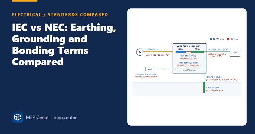
Put an IEC-trained engineer and an NEC-trained engineer in front of the same switchboard and they will describe the same green-yellow conductor in different words. On international projects, that mismatch causes real errors. “Ground” gets read as “neutral”, or the neutral–earth link ends up in two places.
The terms side by side
| IEC / EN (and BS 7671) | NEC (NFPA 70) | What it is |
|---|---|---|
| Earthing | Grounding | Connection to the general mass of earth |
| Neutral conductor (N) | Grounded conductor (usually the neutral) | Current-carrying conductor connected to the earthed point of the source |
| Protective conductor (PE), circuit protective conductor (CPC, UK) | Equipment grounding conductor (EGC) | Conductor that connects exposed metal parts to the earthing point; carries fault current only |
| PEN conductor | Grounded service conductor (neutral bonded at the service) | Combined neutral and protective conductor ahead of the origin |
| Earthing conductor | Grounding electrode conductor (GEC) | Conductor from the main earthing terminal to the electrode |
| Earth electrode | Grounding electrode (rod, ring, concrete-encased “Ufer”) | Conductive part in contact with the soil |
| Foundation earth electrode | Concrete-encased electrode | Electrode in the building foundation |
| Main earthing terminal (MET) | Grounding/bonding point at the service equipment | The point where earthing and bonding conductors meet |
| PEN split at the origin (TN-C-S) | Main bonding jumper | The single neutral-to-earth link of the installation |
| Earthed star point of a generator or transformer | System bonding jumper (separately derived system) | The neutral-to-earth link at a new source |
| Protective equipotential bonding | Bonding | Connecting metal parts so they stay at the same potential |
| Earth fault | Ground fault | A fault between a live conductor and earthed metal |
| RCD, 30 mA additional protection | GFCI (≈ 4–6 mA) for personnel | Residual-current protection of people |
| Earth-fault protection at the origin | GFPE (ground-fault protection of equipment) | Protection of large services against arcing earth faults |
Practical differences beyond the words
| Topic | IEC 60364 practice | NEC practice |
|---|---|---|
| Earthing systems | TN-S, TN-C-S, TT, IT named and chosen per project | Solidly grounded systems, in effect TN-C-S with the neutral bonded at the service only; ungrounded and impedance-grounded systems used in industry |
| PE / EGC sizing | From the phase size (S ≤ 16 → S; ≤ 35 → 16; above → S/2) or an adiabatic check | From the rating of the overcurrent device, using the NEC table |
| Electrode resistance | Target set by system: TT RA × IΔn ≤ 50 V, LPS ≤ 10 Ω where possible | Single rod ≤ 25 Ω, otherwise a supplemental electrode |
| Shock protection | Automatic disconnection with time limits; 30 mA RCD as additional protection | EGC and overcurrent device clear faults; GFCI in specified locations; AFCI in dwellings |
| Colours | PE green-yellow, N blue | EGC green, green-yellow or bare; grounded conductor white or grey |
Typical values — verify with the edition adopted locally.
What this means on a project
- Neither system is “right”. The one adopted by the authority where the building stands applies. Many Middle East and Asian projects mix IEC equipment with US-trained staff, so put a terms table on the general notes sheet.
- Never write just “ground”. Write “PE (EGC)” or “N (grounded conductor)” on drawings that serve both audiences.
- One neutral-to-earth link per source. This is identical in both systems. A second link downstream makes neutral current flow on PE and metalwork, and RCDs or GFPE trip at random.
- Generators and transformers create a new source. The NEC calls this a separately derived system with its own system bonding jumper. In IEC terms the star point is earthed at the set, and a 4-pole changeover is then needed.
- Sizes do not convert exactly. 12 AWG ≈ 3.3 mm², 10 AWG ≈ 5.3 mm². Size a conductor under the code that applies; do not convert it from the other code.
Related reading: TN, TT and IT earthing systems explained, how to measure earth electrode resistance and RCD types AC, A, F and B.
Electrical Power Systems Design for Buildings
35 modules from the MV connection to the socket: transformers, short circuit, protection and selectivity, cable sizing, boards, generators, earthing, surge and lightning protection. Includes 50 % off TEKHAT.
Modules 1–3 are free, no account needed · full course €15,00 one-time
FAQ
Is earthing the same as grounding?
Yes. Earthing is the IEC and British term and grounding is the North American term for connecting a system or equipment to the general mass of earth. The design rules behind the words differ, but the physical concept is the same.
What is the IEC equivalent of an equipment grounding conductor?
The protective conductor (PE), called the circuit protective conductor (CPC) in the UK. It connects exposed metal parts to the earthing point and carries current only during a fault.
What is a main bonding jumper in IEC terms?
It is the connection between the neutral and the protective earthing system at the service. In IEC terms this is where the PEN conductor is split into N and PE at the origin of a TN-C-S installation, and it must exist only once.
Is the NEC grounded conductor the same as the ground wire?
No. The grounded conductor is normally the neutral, which carries load current. The “ground wire” is the equipment grounding conductor, which carries current only during a fault. Mixing them up is a common and dangerous error.
TEKHAT – Single-Line Diagram & Load Schedule
Draw panel single-line diagrams and load schedules in minutes, with breaker, RCD and cable sizing. Buyers of the Electrical Power Systems Design course get 50 % off.
Free install from the Microsoft Store · 30-day trial · licence 20 € for all your devices or €15 per computer on our site
More Electrical articles
- TN-S vs TN-C-S vs TT Earthing: Systems Explained (Plus IT)
- Motor Starting: DOL, Star-Delta, Soft Starter or VFD
- 10 Common Mistakes on Single-Line Diagrams
- Lightning Protection Basics: Rolling Sphere and Mesh Method
- Cable Gland Selection: Size, Armour, IP and Earthing
- RCD Types AC, A, F and B: Which One Where