
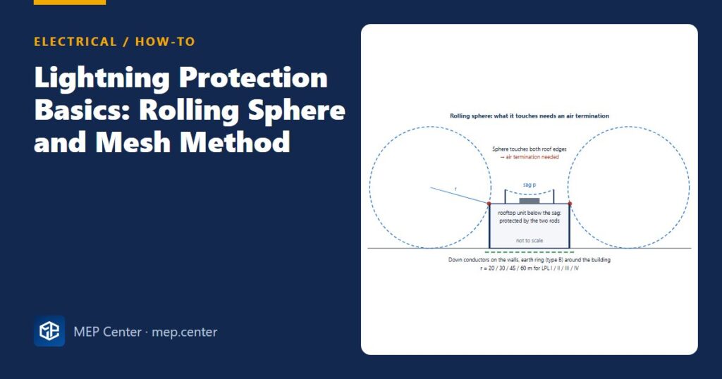
A lightning protection system is often drawn as “a rod on the roof and a cable to the ground”. Then the design review asks which parts of the roof are protected, and nobody can answer. The rolling sphere and the mesh method give a clear yes or no for every edge, parapet and rooftop unit.
| Class (LPL / LPS) | I | II | III | IV |
|---|---|---|---|---|
| Rolling sphere radius | 20 m | 30 m | 45 m | 60 m |
| Maximum mesh size | 5 × 5 m | 10 × 10 m | 15 × 15 m | 20 × 20 m |
| Typical down-conductor spacing | 10 m | 10 m | 15 m | 20 m |
| Design peak current | 200 kA | 150 kA | 100 kA | 100 kA |
Step by step
- Set the class. Run the IEC 62305-2 risk assessment, or follow the national rule for the building type. Why: the class drives every other number, and “class I everywhere” wastes money.
- Draw the sphere on sections and elevations. In CAD, draw a circle of radius r and roll it over the building outline, touching the ground and the structure. Why: it shows exactly which edges, corners and tall parts can be struck.
- Put air terminations wherever the sphere touches. On a flat roof, that means conductors on all edges, parapets and ridges, plus a mesh no larger than the class allows. Why: most strikes hit corners and edges, not the middle of the roof.
- Protect rooftop equipment with rods. Between two rods or conductors the sphere sags by p = r − √(r² − (d/2)²), where d is the spacing. The equipment must stay below the rod tips minus p. Why: a unit that sticks out of the protected zone becomes the air terminal.
- Keep the separation distance. Calculate s = ki × (kc / km) × l between the LPS and metal parts or cables that are not bonded to it. Why: otherwise the strike flashes over into the building’s services.
- Run the down conductors. Use at least two, spread evenly and preferably at the corners, at the class spacing. Fit a test joint 0.3–1 m above ground on each one. Why: several paths split the current and lower the voltages along each conductor.
- Earth and bond. A type B ring about 0.5 m deep and about 1 m from the walls, or a foundation electrode, bonded to the main earthing terminal. Add a Type 1 SPD at the origin of the installation. Why: part of the lightning current enters the building through the incoming services.
Worked example: rods over a rooftop unit
Sag: p = 45 − √(45² − 5²) = 45 − √2000 = 45 − 44.72 = 0.28 m.
Protected height at mid-span: 2.5 − 0.28 = 2.22 m > 1.5 m → protected.
Same layout in class I (r = 20 m): p = 20 − √(400 − 25) = 20 − 19.36 = 0.64 m → 1.86 m > 1.5 m → still protected.
Separation distance: class III, ki = 0.04, air km = 1, four or more down conductors with a ring kc ≈ 0.44, l = 20 m to the nearest bonding point → s ≈ 0.04 × 0.44 × 20 ≈ 0.35 m. Keep the unit’s metal casing and cables at least this far from the rods and conductors, or bond them.

Common slips
- Forgetting the walls of tall buildings. On a building taller than r, the sphere touches the facade above height r. Those upper edges and corners need air terminations too.
- Using “special” air terminals to cover a large radius. Early streamer emission devices are not recognised by IEC 62305. Design with the sphere, mesh or angle method.
- Undersized conductors. Copper 50 mm² (Ø 8 mm round) and hot-dip galvanised steel 50 mm² are the usual minimums for air terminations and down conductors.
- No bonding of roof metalwork. Handrails, ducts and cable trays within the separation distance must be bonded or moved.
- Earth ring not bonded to the main earth. The LPS earth and the electrical earth must be one system. See earthing systems explained and how to test the earth electrode.
- No surge protection. An LPS without a Type 1 SPD at the origin lets part of the strike into the boards. See how to connect an SPD.
US projects follow NFPA 780, which also uses a rolling sphere, typically 46 m (150 ft) for ordinary structures, with air terminals at most about 6 m (20 ft) apart along roof edges.
Typical values — verify with the edition adopted locally.
Electrical Power Systems Design for Buildings
35 modules from the MV connection to the socket: transformers, short circuit, protection and selectivity, cable sizing, boards, generators, earthing, surge and lightning protection. Includes 50 % off TEKHAT.
Modules 1–3 are free, no account needed · full course €15,00 one-time
FAQ
What rolling sphere radius should I use?
Under IEC 62305 the radius follows the protection class: 20 m for class I, 30 m for II, 45 m for III and 60 m for IV. The class comes from the risk assessment or the national rule for the building type. NFPA 780 uses 46 m (150 ft) for ordinary structures.
How do I calculate the sag of the sphere between two rods?
Use p = r − √(r² − (d/2)²), where d is the distance between the rods. For r = 45 m and d = 10 m, p is about 0.28 m, so equipment between the rods must stay at least 0.28 m below the rod tips.
When should I use the mesh method instead of the rolling sphere?
Use a mesh on flat or gently sloping roofs, with conductors on all edges and a cell size no larger than the class allows (5 to 20 m). Use the rolling sphere for complex shapes, tall parts and rooftop equipment. Most designs use both.
TEKHAT – Single-Line Diagram & Load Schedule
Draw panel single-line diagrams and load schedules in minutes, with breaker, RCD and cable sizing. Buyers of the Electrical Power Systems Design course get 50 % off.
Free install from the Microsoft Store · 30-day trial · licence 20 € for all your devices or €15 per computer on our site
More Electrical articles
- Standby Generator Sizing: A Quick Method That Works
- EV Charger Installation: An Electrical Checklist
- How to Measure Earth Electrode Resistance (Fall-of-Potential)
- Motor Starting: DOL, Star-Delta, Soft Starter or VFD
- RCD Types AC, A, F and B: Which One Where
- Cable Sizing for Voltage Drop: Formula, Limits and Worked Example