
Duct sizing is a balancing act: small ducts save ceiling space and money but cost fan energy and make noise, while large ducts are quiet and efficient but do not fit. Many designers stop once every duct “looks right” for velocity, yet the job is not finished until the index run pressure drop is calculated, because that number selects the fan. This guide gives you the methods, the typical values and a fully worked floor branch.
- Size low-pressure comfort ducts by equal friction at about 0.8–1.0 Pa/m, then check velocities against noise limits.
- Velocity pressure pv = 0.6 v² Pa. Every fitting loses ζ × pv, and fittings plus the terminal are often more than half the total.
- A mitred elbow without turning vanes costs as much as 20–30 m of straight duct.
- Find the index run (highest total pressure loss, not always the longest path) and give its value to the fan selection.
- Prefer circular duct; keep rectangular aspect ratios at 3:1 or less.
- Specify a leakage class (class C is easy with factory-sealed spiral duct) and keep flexible duct to 1.5–2 m.
What duct sizing has to deliver
A duct system must bring the design airflow to every terminal quietly, with minimum fan energy, space and cost, while staying airtight, cleanable and fire-safe. The workflow:
- Airflow at each terminal, from the room loads and ventilation requirements.
- Route, coordinated with structure and other services.
- Sizing method and limits (friction rate, velocity, noise).
- Size each segment; calculate friction and fitting losses.
- Identify the index run and the external pressure for the fan.
- Check balance, noise, leakage, insulation, fire dampers and access.
The terminal airflows come from the room loads. If you still need those, start with our cooling load calculation basics.
Three pressures you need to keep apart
ptotal = pstatic + pvelocity, pv = ½ ρ v² ≈ 0.6 v² (Pa, with v in m/s and ρ = 1.2 kg/m³)
| Velocity (m/s) | 2 | 4 | 6 | 8 | 10 | 12 |
|---|---|---|---|---|---|---|
| Velocity pressure (Pa) | 2.4 | 9.6 | 21.6 | 38.4 | 60 | 86 |
Total pressure always falls along the flow; static pressure can rise where the air slows down (static regain). Calculate ducts and fans in total pressure.
Friction loss and the friction chart
Friction follows the Darcy–Weisbach equation; in practice you use a friction chart or software: enter with the airflow and friction rate, read the diameter, round to a standard size and read back the actual friction. Galvanised spiral duct has a roughness of about 0.09 mm.
Standard circular sizes include 100, 125, 160, 200, 250, 315, 400, 500, 630, 800 and 1000 mm. For galvanised circular duct at standard air:
| Airflow | Ø at 1.0 Pa/m | Size used | Actual R (Pa/m) | v (m/s) |
|---|---|---|---|---|
| 0.10 m³/s (100 L/s) | 187 mm | 200 | 0.71 | 3.2 |
| 0.20 m³/s | 241 mm | 250 | 0.84 | 4.1 |
| 0.40 m³/s | 312 mm | 315 | 0.96 | 5.1 |
| 0.80 m³/s | 406 mm | 400 | 1.07 | 6.4 |
| 1.20 m³/s | 473 mm | 500 | 0.76 | 6.1 |
The velocities, friction rates and ζ values in this guide are typical – verify with the edition adopted locally, the project acoustic criteria and manufacturer data.
Velocity limits – noise decides
Regenerated noise rises steeply with velocity, and pressure loss with its square. Typical maximum velocities for comfort systems:
| Duct location | Quiet spaces (NR 25–30) | Offices (NR 35–40) | Industrial / plant |
|---|---|---|---|
| Mains in shafts and plant rooms | 6–8 m/s | 8–10 m/s | 10–15 m/s |
| Mains above occupied ceilings | 4–5 m/s | 5–7 m/s | 8–10 m/s |
| Branch ducts | 3–4 m/s | 4–5 m/s | 6–8 m/s |
| Runouts to terminals | 2–2.5 m/s | 2.5–3.5 m/s | 4–5 m/s |
Keep outdoor air louvres to 2.0–2.5 m/s through the free area against rain.
Choosing a sizing method
Equal friction
All ducts are sized for the same friction rate, typically 0.8–1.0 Pa/m (0.6 Pa/m in quiet buildings, up to 1.5–2 Pa/m in industrial or tight work). It is simple and gives sensible velocities automatically. Its weakness: branches near the fan have far less pressure drop than the index run and must be throttled.
Velocity method
Pick velocities segment by segment and calculate the friction. Use it for simple exhaust and for conveying (dust, grease), where a minimum velocity keeps material airborne.
Static regain
Each segment after a take-off is sized so the static pressure regained from the velocity drop, R × (pv,up − pv,down) with R ≈ 0.75, offsets the next segment’s losses. Take-offs then see nearly equal static pressure and the system self-balances. It pays off on long, high-velocity mains such as VAV mains and risers in tall buildings.
Fitting losses – the ζ coefficient
Δpfitting = ζ × pv, with pv at the velocity the data source refers to (usually downstream or branch velocity).
| Fitting | Typical ζ |
|---|---|
| 90° circular elbow, smooth, r/D 1.5 | 0.15 |
| 90° rectangular mitred elbow, no vanes | 1.1–1.3 |
| Mitred elbow with turning vanes | 0.25–0.4 |
| Tee, straight-through run | 0.05–0.2 |
| 90° branch take-off | 0.6–1.2 |
| 45° or conical take-off | 0.3–0.6 |
| Volume damper, fully open | 0.2–0.5 |
| Duct exit into a plenum | 1.0 |
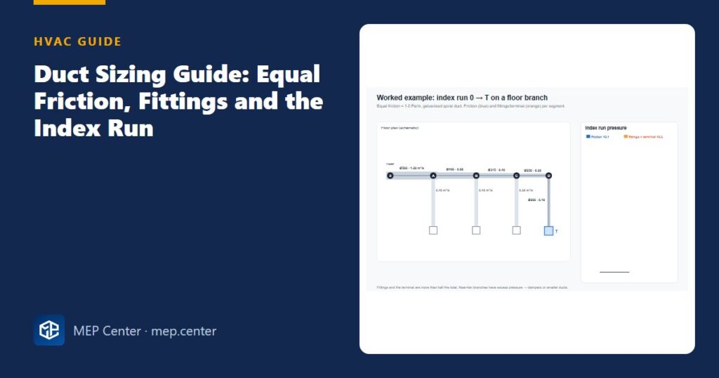
Worked example – a floor branch, equal friction
Inputs
- Office floor, normal acoustic criteria (NR 35), galvanised spiral duct, standard air, target ≈ 1.0 Pa/m.
- 0–A: 1.20 m³/s, 12 m, one smooth elbow (ζ 0.15) and the floor fire damper (ζ 0.30).
- A–B: 0.80 m³/s, 10 m, tee run (ζ 0.10). B–C: 0.40 m³/s, 10 m, tee run + smooth elbow (ζ 0.25). C–D: 0.20 m³/s, 8 m, tee run (ζ 0.10).
- D–T: 0.10 m³/s, 90° branch take-off (ζ 0.80) + volume damper (ζ 0.20), 4 m rigid Ø200, then 1.5 m flexible duct, plenum box and diffuser (25 Pa from the catalogue at 100 L/s).
Step by step
For each segment: v = q / A, pv = 0.6 v², friction = R × L, fittings = Σζ × pv.
| Segment | Ø (mm) | v (m/s) | pv (Pa) | R × L (Pa) | Σζ × pv (Pa) | Total (Pa) |
|---|---|---|---|---|---|---|
| 0–A | 500 | 6.11 | 22.4 | 0.76 × 12 = 9.1 | 0.45 × 22.4 = 10.1 | 19.2 |
| A–B | 400 | 6.37 | 24.3 | 1.07 × 10 = 10.7 | 0.10 × 24.3 = 2.4 | 13.1 |
| B–C | 315 | 5.13 | 15.8 | 0.96 × 10 = 9.6 | 0.25 × 15.8 = 4.0 | 13.6 |
| C–D | 250 | 4.07 | 10.0 | 0.84 × 8 = 6.7 | 0.10 × 10.0 = 1.0 | 7.7 |
| D–T rigid | 200 | 3.18 | 6.1 | 0.71 × 4 = 2.8 | 1.00 × 6.1 = 6.1 | 8.9 |
| Flexible duct | 200 | 3.18 | – | ≈ 2.1 × 1.5 = 3.2 | – | 3.2 |
| Plenum + diffuser | – | – | – | – | 25.0 | 25.0 |
| Index run | 42.1 | 48.6 | 90.7 |
Result
The floor branch needs ≈ 91 Pa at node 0. Add the riser, the AHU ductwork and the intake and exhaust to get the external pressure for the fan.
Sanity check
Velocities fall from 6.1 to 3.2 m/s along the run – inside the office limits for ceiling mains and runouts. Check one velocity by hand: 1.20 / (π/4 × 0.5²) = 1.20 / 0.196 = 6.11 m/s ✓. Fittings and the terminal (48.6 Pa) are more than half of the total, which is normal; a calculation where fittings are “10 % extra” is the one to distrust.
Balancing – what happens to the short branches
The first branch at A needs only the 0–A segment (19.2 Pa), its own branch run (about 25 Pa) and its diffuser (25 Pa): roughly 70 Pa. About 20 Pa must be absorbed by its volume damper. That is fine. Excess pressures above about 50–80 Pa at dampers close to diffusers make noise – move the damper back to the branch start or size the branch smaller so the duct absorbs the pressure. Put dampers on every branch, in accessible places, and the commissioning engineer will thank you.
Rectangular versus circular
Circular spiral duct uses the least metal for a given area, leaks least, is stiffest and quietest. Rectangular duct fits flat ceiling voids. To compare them, use the friction-equivalent diameter (Huebscher):
De = 1.30 × (a × b)0.625 / (a + b)0.25 (a, b = sides in mm)
500 × 400 mm gives De = 488 mm. A 600 × 350 duct matches Ø500 for friction but uses 21 % more sheet metal; 1000 × 200 uses 53 % more and still has more friction. Keep aspect ratios at 3:1 or less (4:1 as a normal maximum). De gives equal friction at equal airflow, not equal velocity – calculate the rectangular velocity from its own area.
From the index run to the fan
The fan must deliver the design flow against the index run plus everything upstream: AHU sections, filters at their final (dirty) pressure drop, coils, louvres. Two relationships keep you honest:
- Fan laws: +10 % flow on the same system needs +21 % pressure and +33 % power. Oversized “safety” flows are expensive.
- Air power = q × Δp. 2.0 m³/s × 1150 Pa = 2.30 kW of air power; at realistic fan and motor efficiencies this becomes about 3.65 kW electrical, a specific fan power of 1.83 kW/(m³/s).
Avoid elbows directly at the fan outlet or inlet – the “system effect” robs the fan of pressure the catalogue promised. The AHU side of the story, including coils and the psychrometric process, is in our psychrometric chart and AHU process guide.
Leakage, insulation and flexible duct
- Leakage classes (EN 12237 / EN 1507): each class is three times tighter than the one before. For 300 m² of duct at 250 Pa carrying 2000 L/s, class A leaks about 14.7 %, B 4.9 %, C 1.6 %, D 0.5 %. Class B is a common minimum, class C is recommended.
- Cold ducts: a 13 °C supply duct in a 30 °C, 70 % RH void needs only about 9 mm of insulation to stay above the 23.9 °C dew point – but the vapour barrier must be continuous, or water forms under the insulation.
- Flexible duct: 2–5 times the friction of rigid duct even fully extended; keep it to about 1.5–2 m, supported, and never through fire-separating elements.
Common mistakes
- Sizing by velocity alone and never calculating the index run.
- Adding “10 % for fittings” when fittings and terminals are often more than half the loss.
- Mitred elbows without vanes in mains; elbows directly at the fan.
- Flat rectangular ducts (6:1, 8:1) to squeeze into a void that was never coordinated.
- Long, compressed, sagging flexible duct.
- No balancing dampers, or dampers above fixed ceilings.
- Leakage class not specified or not tested.
- Fire dampers without access doors, or installed outside their tested method.
Quick checklist
- Terminal airflows taken from the room schedule.
- Sizing method, target friction and velocity limits stated; noise criteria checked.
- Index run calculated with friction, fittings and terminal losses.
- Balance checked; dampers located; excess pressure at dampers moderate.
- Circular ducts where possible; rectangular ≤ 3:1.
- Pressure class, leakage class and testing extent specified.
- Cold ducts insulated with a continuous vapour barrier.
- Fire and smoke dampers per tested installation, with access doors.
HVAC Systems Design — Heating, Cooling & Ventilation
28 modules from heat loss to plant room: boilers, heat pumps, cooling loads, psychrometrics, AHUs and ductwork. The VRF course is included.
Modules 1–3 are free, no account needed · full course €15,00 one-time
FAQ
What friction rate should I use for duct sizing?
For low-pressure comfort systems, 0.8–1.0 Pa/m is the usual equal friction target. Use about 0.6 Pa/m in quiet buildings and up to 1.5–2 Pa/m only where space is very tight or noise does not matter.
What is the maximum air velocity in an office duct?
Typical limits are 8–10 m/s for mains in shafts, 5–7 m/s for mains above office ceilings, 4–5 m/s for branches and 2.5–3.5 m/s for runouts to diffusers. Check them against the project’s acoustic criteria.
What is the index run?
It is the path from the fan to the terminal with the highest total pressure loss, including friction, fittings and the terminal itself. It is not always the longest path, and its value sets the fan’s external pressure.
How do I convert a rectangular duct to an equivalent round duct?
Use the Huebscher formula De = 1.30 × (a × b)^0.625 / (a + b)^0.25, with a and b in mm. For example, 500 × 400 mm is equivalent to about 488 mm round for friction at the same airflow.
How much do duct fittings add to the pressure loss?
Often more than half of the total. A mitred elbow without vanes at 6 m/s loses about 26 Pa, the same as 26 m of straight duct at 1 Pa/m, so calculate fittings one by one.