
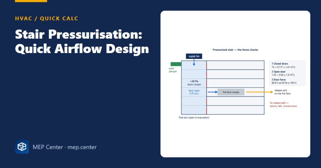
A pressurised stair has to meet three conditions at once: enough pressure to keep smoke out with the doors closed, enough air velocity through an open door, and a door that people can still open. The fan size falls out of the first two; the third catches designs that over-pressurise. Here is a quick estimate you can do before the specialist calculation.
The formulas
Leakage through a closed door: Q = 0.83 × A × Δp0.5 (Q in m³/s, A = leakage area in m², Δp in Pa).
Open door: Q = Adoor × v (v = required air velocity through the doorway, m/s).
Door opening force: F = Fdc + (W × A × Δp) / (2 × (W − d)), with Fdc = door closer force (N), W = door width (m), A = door area (m²), d = distance from the handle to the door edge (m).
Criteria side by side
| Criterion | European approach (EN 12101 series) | US approach (NFPA 92) |
|---|---|---|
| Pressure, doors closed | Traditionally ≈ 50 Pa for many system classes | Minimum ≈ 12.5 Pa in sprinklered buildings; higher without sprinklers |
| Velocity, doors open | ≈ 0.75 m/s (some evacuation classes); 2 m/s (firefighting classes) | No fixed door velocity; minimum pressure differences maintained with the design number of doors open |
| Door opening force | 100 N | 133 N (30 lbf), per life-safety code |
EN 12101-6 is being superseded by EN 12101-13; check which edition and system class your fire strategy uses. Which approach applies is set by the local code and the fire engineer, not by preference.
Worked example: 12-door stair
Closed doors: 0.83 × 0.02 × √50 = 0.83 × 0.02 × 7.07 = 0.117 m³/s per door → × 12 = 1.41 m³/s; + 25–50 % unidentified leakage → 1.8–2.1 m³/s.
Open door: 1.8 × 0.75 = 1.35 m³/s, plus the 11 closed doors at the remaining ≈ 10 Pa: 11 × 0.83 × 0.02 × 3.16 = 0.58 m³/s → ≈ 1.9 m³/s.
Fan: both cases are similar here → about 2.1 m³/s before duct leakage and margins. With a 2 m/s criterion the open door alone would need 3.6 m³/s and would govern by far.
Door force (0.9 × 2.1 m door, A 1.89 m², closer 40 N, handle 60 mm from the edge): 40 + (0.9 × 1.89 × 50) / (2 × 0.84) = 40 + 50.6 = 90.6 N ✓ (≤ 100 N, little margin).
Sanity check: if all doors close and the pressure rises to 80 Pa, F = 40 + 81 = 121 N ✗ — this is why pressure relief is essential.
Design checks that are often missed
- Release path: without vents, a shaft or mechanical extract on the fire floor, the air through the open door has nowhere to go and the velocity criterion fails.
- Pressure relief: a barometric relief damper or a variable-speed fan controlled on stair pressure keeps the door force below the limit when doors close.
- Intake position: outdoor air from a point that smoke cannot reach — never next to smoke exhaust or car-park outlets.
- Tall buildings: stack effect changes the pressure difference with height; use several injection points.
- Power and controls: fire-rated supplies and cables, and a cause-and-effect matrix with the fire alarm.
- Commissioning: measure pressure, door velocity and door force on site; see the HVAC commissioning checklist.
Related reading: fire alarm cause and effect matrix, car park ventilation with jet fans and the duct sizing guide for the supply shaft.
Typical values — verify with the edition adopted locally. This is a quick estimate; the pressurisation system is a life-safety system and its final design follows the fire strategy and the specialist calculation.
HVAC Systems Design — Heating, Cooling & Ventilation
28 modules from heat loss to plant room: boilers, heat pumps, cooling loads, psychrometrics, AHUs and ductwork. The VRF course is included.
Modules 1–3 are free, no account needed · full course €15,00 one-time
FAQ
What pressure is used for stair pressurisation?
European practice has traditionally used about 50 Pa with the doors closed for many system classes. NFPA 92 sets a minimum of about 12.5 Pa in sprinklered buildings and higher values without sprinklers.
How do I estimate the airflow for a pressurised stair?
Calculate leakage through all closed doors with Q = 0.83 × A × √Δp and add 25–50 % for unidentified leakage. Then calculate the open-door case as door area times required velocity plus leakage at the reduced pressure, and use the larger result.
What is the maximum door opening force?
About 100 N in European practice and 133 N (30 lbf) in US life-safety codes. Pressure relief or fan speed control is needed so that the force stays below the limit when all doors are closed.