
A fan coil picked from the first catalogue column usually looks fine on paper and then leaves the room 2 K too warm, or keeps the occupants awake at high speed. The catalogue rates the unit at conditions your room will never see. Here is a selection sequence that avoids both problems.
Step by step
- Take the room sensible load from the cooling load calculation (here 2.64 kW sensible, 0.17 kW latent). Why: the thermostat reacts to dry-bulb temperature; total capacity can hide a sensible shortfall.
- Fix the water temperatures to match the plant, for example 7/13 °C (ΔT 6 K). Why: a unit selected at 7/12 °C on a 7/13 °C plant delivers less, and a terminal ΔT that differs from the plant ΔT causes low-ΔT problems at the chiller.
- Define the real entering-air condition. Room 24 °C plus about 1 K of stratification and ducted return gives 25 °C DB / 18 °C WB. Why: catalogue ratings at 27 °C DB / 19 °C WB overstate capacity in a 24 °C room.
- Add up the external static pressure (ESP): short duct with bends 10–25 Pa, diffuser 10–25 Pa, return grille and plenum 5–15 Pa, short flexible 5–15 Pa, attenuator 20–50 Pa. Here ≈ 40 Pa → a medium-static unit (30–80 Pa). Why: underestimated ESP means less airflow and less capacity.
- Select at medium speed the smallest unit whose sensible capacity meets the load and whose noise meets the criterion. Why: high speed is the reserve for morning pull-down; units selected at high speed are noisy on the design day.
- Set the water flow from the total coil load: q = Φ / (4.19 × ΔT) L/s, and set the PICV to it. Why: over-flowing coils give little extra capacity and destroy the plant ΔT.
- Check heating (4-pipe or change-over): fan-coil heating output is roughly proportional to the water-to-air temperature difference, so a unit giving 3.2 kW at 70/60 °C gives only about 1.6 kW at 45/40 °C. Why: low-temperature heat sources halve the heating capacity.
- Detail the condensate: insulated, sloped drain pan; drain fall ≥ 1 % (2 % preferred); trap to the manufacturer’s detail; air break into the condensate main. Why: a dripping ceiling is the most visible FCU failure.
Worked example: west office
Candidates (illustrative manufacturer data at these conditions):
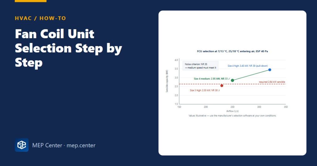
Size 3, high speed: 230 L/s, 2.55 kW sensible, NR 38 → fails on capacity and noise.
Size 4, medium speed: 250 L/s, 2.85 kW sensible, 3.40 kW total, NR 33 → passes.
Size 4, high speed: 320 L/s, 3.45 kW sensible, NR 39 → pull-down reserve only.
Selection: Size 4 at medium speed — 2.85 ≥ 2.64 kW, NR 33 ≤ NR 35.
Water flow: total coil load at the actual condition ≈ 3.1 kW → 3.1 / (4.19 × 6) = 0.123 L/s (≈ 0.44 m³/h); PICV set to 0.123 L/s.
Condensate: about 0.4–0.7 L/h at peak.
Sanity check: 2.85 kW at 250 L/s means an air temperature drop of 2 850 / (1.2 × 250) = 9.5 K across the coil — a normal value for an FCU.
2-pipe or 4-pipe?
A 2-pipe system carries either chilled or hot water, so the whole circuit is in one mode at a time. That is fine for apartments or hotels in mild climates with seasonal change-over. Deep-plan offices, where the north façade wants heat while the south façade and core want cooling on the same morning, normally need 4-pipe units (or façade-zoned 2-pipe circuits, or electric heaters for the shoulder seasons).
Common selection traps
- Selecting on total capacity at 27/19 °C catalogue conditions.
- Selecting at high speed — noise complaints, no reserve.
- Long or crushed flexible ducts: they can push ESP from 40 to 75 Pa and cut the airflow by almost a fifth.
- Terminal ΔT different from the plant ΔT.
- No access to the filter, valve set and drain pan once the ceiling is closed.
Loads come from cooling load calculation basics. For the drain see condensate drain and trap design, for the pumps chilled water pump head estimate, and for all-air alternatives VAV box selection.
Typical values — verify with the edition adopted locally and with certified manufacturer data.
HVAC Systems Design — Heating, Cooling & Ventilation
28 modules from heat loss to plant room: boilers, heat pumps, cooling loads, psychrometrics, AHUs and ductwork. The VRF course is included.
Modules 1–3 are free, no account needed · full course €15,00 one-time
FAQ
Should a fan coil be selected on sensible or total capacity?
On sensible capacity, because the room thermostat controls dry-bulb temperature. Check total capacity afterwards for the latent load and use it to set the water flow.
Why select a fan coil at medium speed?
Medium speed keeps the noise lower for most hours and leaves high speed as a reserve for morning pull-down. A unit that needs high speed on the design day is usually too noisy.
What external static pressure should I allow for a ducted fan coil?
Add up the actual components: a short duct with bends, the diffuser, the return grille and any flexible duct typically total 30–50 Pa. An attenuator adds 20–50 Pa. Select a medium-static unit for that range.