
The pump schedule is due before the pipe routes are final, and someone wants a head figure today. A guess of “30 m to be safe” produces a pump that runs throttled for 25 years; a sensible estimate built from the index circuit takes ten minutes and stays close to the final calculation.
The formula
H = R × L × (1 + k) + Δpevap + Δpcoil + Δpvalve + Δpstrainer + Δpother
- R: average friction rate of the index run in Pa/m (chilled water mains are usually sized at 100–300 Pa/m).
- L: length of the index circuit, supply and return, in m. The index circuit is the one with the highest total loss, usually the furthest coil but not always.
- k: fittings and valves allowance; 0.5 (50 % of straight pipe) is a reasonable early-stage figure.
- Δpevap: chiller evaporator at design flow, from manufacturer data.
- Δpcoil: water side of the index coil, typically up to 30–50 kPa (see AHU sizing quick rules).
- Δpvalve: the control valve at the index coil; a pressure-independent valve needs its minimum operating Δp, often 15–30 kPa.
Convert with 1 m head = 9.81 kPa. In a closed loop the static height cancels out (the water going up the riser is balanced by the water coming down), so do not add the building height. That is only right for open circuits such as condenser water to a cooling tower, where the lift from the basin water level to the spray inlet is real.
Worked example
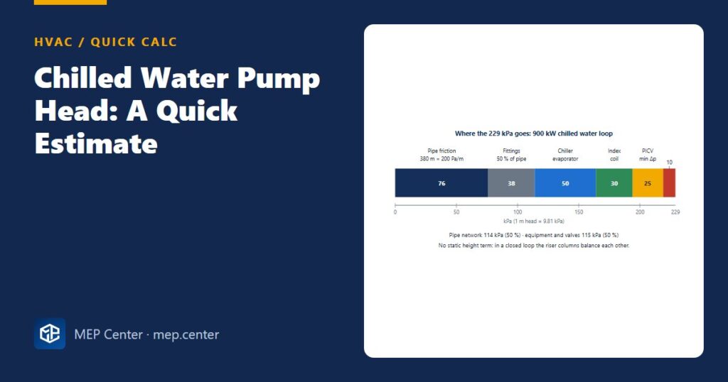
Data: primary-only variable flow plant, 900 kW at 7/13 °C. Flow q = 900 / (4.19 × 6) = 35.8 L/s (129 m³/h). Index circuit 380 m of pipe (supply + return), average 200 Pa/m.
| Item | kPa |
|---|---|
| Straight pipe 380 m × 200 Pa/m | 76 |
| Fittings and valves, 50 % of straight pipe | 38 |
| Chiller evaporator (manufacturer data) | 50 |
| Index AHU coil | 30 |
| PICV minimum operating Δp | 25 |
| Strainer, with fouling allowance | 10 |
| Pump head | 229 kPa ≈ 23.3 m |
Hydraulic power: 0.0358 m³/s × 229 000 Pa = 8.2 kW. With pump efficiency 0.75 and motor + VSD 0.90 (wire-to-water 0.68): 8.2 / 0.68 ≈ 12.1 kW electrical.
Sanity check: cooling delivered per kW of pump power = 900 / 12.1 ≈ 74. Values below about 40–50 point to excessive head or a low ΔT.
Rule-of-thumb table
| Item | Early-stage value |
|---|---|
| Pipe friction rate, mains | 100–300 Pa/m (often ≤ 250) |
| Fittings and valves | + 50 % of straight pipe friction |
| Quick network figure | ≈ 0.3 kPa per metre of index circuit (200 Pa/m × 1.5) |
| Coil, water side | ≤ 30–50 kPa |
| PICV minimum Δp | 15–30 kPa |
| Strainer | ≈ 10 kPa including fouling |
| Wire-to-water efficiency | ≈ 0.65–0.70 (pump 0.75 × motor/VSD 0.90) |
| Flow per kW | 0.0398 L/s at 6 K; 0.0477 L/s at 5 K |
Pipe sizing and friction rates are covered in hydronic pipe sizing; the same Darcy–Weisbach method applies to chilled water.
Mistakes that inflate the head
- Adding the building height to a closed loop.
- Hidden margins on every line: 10 % here and 20 % there end as a pump that runs throttled or at excess flow. Put one stated margin at the end, if any.
- Measuring the differential pressure at the pump instead of near the index circuit: the pump then holds full head all year.
- Forgetting glycol: with 30 % propylene glycol the flow rises by about 6 % and pressure drops rise by 20–50 %.
At 50 % flow, the worked pump uses about 2.6 kW with a fixed index-circuit set point (55 kPa offset) and about 1.9 kW with set-point reset from valve positions, far from the ideal cube law but far better than constant speed. Select the duty point (35.8 L/s at 229 kPa) near the pump’s best-efficiency point, with a VSD and a standby pump.
Typical values — verify with the edition adopted locally and with manufacturer data.
HVAC Systems Design — Heating, Cooling & Ventilation
28 modules from heat loss to plant room: boilers, heat pumps, cooling loads, psychrometrics, AHUs and ductwork. The VRF course is included.
Modules 1–3 are free, no account needed · full course €15,00 one-time
FAQ
Do I add the building height to a chilled water pump head?
No. In a closed loop the water column going up is balanced by the column coming down, so the pump only overcomes friction. Static height counts only in open circuits such as cooling tower condenser water.
What is a typical chilled water pump head?
For a commercial building loop it often falls between about 150 and 300 kPa (15–30 m), depending on the index run and the equipment. The worked 900 kW example with a 380 m index circuit gives 229 kPa, about 23.3 m.
How do I convert pump head from kPa to metres?
Divide by 9.81: 229 kPa / 9.81 = 23.3 m of water. One metre of head equals about 9.81 kPa or 0.098 bar.