
An enclosed car park needs a lot of air, but only for short periods: rush hours and, in a fire, smoke clearance. Jet fans replace the big duct network with small impulse fans under the soffit. The first layout and fan sizes can be estimated in a few lines, before the CFD study confirms them.
Step 1: the airflow
| Basis | Typical value | Where it is used |
|---|---|---|
| Area rate (ASHRAE 62.1 enclosed parking) | ≈ 3.7 L/s·m² (0.75 cfm/ft²) | US-based codes; reductions with gas-sensing control (check the edition) |
| Air changes, normal | ≈ 6 ACH | UK and some European practice |
| Air changes, smoke clearance | ≈ 10 ACH | UK practice for jet fan systems |
| Emission-based | From car movements and allowable CO | Large or unusual car parks |
The local code decides which rule applies. The fans usually run at low speed most of the time under CO and NO₂ control and reach full speed only at peak traffic or in fire mode.
Step 2: jet fan thrust and count
A jet fan is rated by its thrust, the momentum of its jet:
T = ρ × q × v, with v = q / A, so q = √(T × A / ρ)
where T is the thrust in N, ρ = 1.2 kg/m³, q the fan airflow in m³/s, v the outlet velocity in m/s and A the outlet area in m². The jet drags the surrounding air with it, so the air moved across the floor is many times the fan’s own airflow.
For a first layout, allow one 50 N fan per about 400–600 m², spaced 30–40 m in the throw direction and 15–20 m apart laterally, so each jet hands over to the next with no dead zones behind ramps, cores or deep beams. Orient fans parallel to downstand beams, or mount them in the bays.
Worked example: basement car park 100 × 50 m = 5000 m², clear height 3.0 m, volume 15 000 m³.
- 62.1 rate: 5000 × 3.7 = 18 500 L/s = 18.5 m³/s (66 600 m³/h), ≈ 4.4 ACH.
- 6 ACH: 15 000 × 6 = 90 000 m³/h = 25.0 m³/s.
- 10 ACH smoke clearance: 150 000 m³/h = 41.7 m³/s. If this is the fire strategy’s case, the extract fans are sized for it (high-temperature rated) and run at reduced speed in normal mode.
- Jet fan, Ø315 mm outlet (A = 0.0779 m²) at 50 N: q = √(50 × 0.0779 / 1.2) = 1.80 m³/s, v = 1.80 / 0.0779 = 23 m/s.
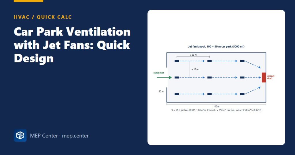
- Count: 5000 / 500 ≈ 10 fans. Three rows of three at about 33 m along and 17 m across give 9 fans, 556 m² each, inside the 400–600 m² range.
- Gas sensors at one per 400–700 m²: 5000 / 700 to 5000 / 400 → 8–13 sensors at 1.5–1.8 m height.
Sanity check: 25.0 m³/s × 3600 / 15 000 m³ = 6.0 ACH and 18 500 L/s / 5000 m² = 3.7 L/s·m², so both rates back-calculate. CFD then confirms the CO distribution and the fire-mode performance.
Rule-of-thumb table
| Item | Typical value |
|---|---|
| Jet fan thrust | 25–100 N (50 N common) |
| Spacing along / across the flow | 30–40 m / 15–20 m |
| Floor area per 50 N fan | ≈ 400–600 m² |
| CO sensors | 1 per 400–700 m², at 1.5–1.8 m |
| Staging (illustrative) | Low speed at CO 25–30 ppm or NO₂ 0.5–1 ppm; high at CO 50 ppm or NO₂ 1–2 ppm; alarm at CO 100 ppm |
| Fire-rated fans | For example 300 °C for 60–120 min, as the fire strategy requires |
Things that make or break the design
- Replacement air paths. The air must come in somewhere: ramps and dedicated intakes. Check they are not closed by roller shutters or fire shutters when the fans run.
- NO₂ as well as CO. Modern fleets emit relatively more NO₂ from diesel engines; sense both where diesel vehicles are expected.
- Demand control. Running at 50 % flow for 90 % of the time and full speed for 10 % cuts fan energy to about 21 % of continuous full-speed running.
- Fire mode is a separate design. Smoke clearance after the fire and smoke control for firefighter access are different objectives. The fire strategy sets the objective, and fire mode overrides all normal control from the fire panel.
For the ventilation rates of the occupied parts of the building, see ASHRAE 62.1 vs EN 16798; for the extract ducts and shafts, the duct sizing guide.
Typical values — verify with the edition adopted locally.
HVAC Systems Design — Heating, Cooling & Ventilation
28 modules from heat loss to plant room: boilers, heat pumps, cooling loads, psychrometrics, AHUs and ductwork. The VRF course is included.
Modules 1–3 are free, no account needed · full course €15,00 one-time
FAQ
How many air changes does a car park need?
UK-style practice uses about 6 ACH for normal ventilation and 10 ACH for smoke clearance; ASHRAE 62.1 uses an area rate of about 3.7 L/s per m² (0.75 cfm/ft²), which is about 4.4 ACH for a 3 m high car park. The local code decides.
How many jet fans do I need for a car park?
For a first layout, about one 50 N jet fan per 400–600 m², spaced 30–40 m along the airflow and 15–20 m across it. A 5000 m² floor needs roughly 9–10 fans, confirmed by CFD.
How do I calculate jet fan airflow from thrust?
Use q = √(T × A / ρ). A 50 N fan with a Ø315 mm outlet (0.0779 m²) moves √(50 × 0.0779 / 1.2) = 1.80 m³/s at about 23 m/s.