
The architect wants to know how big the plant room must be, and the AHU selection software is not open yet. You need an airflow, a casing cross-section, a coil duty and a footprint you can defend in ten minutes, and that later matches the manufacturer’s selection.
Step 1: airflow
For a recirculating unit serving a cooled space, the supply airflow comes from the room sensible load and the supply temperature difference:
q = Qs / (1.2 × ΔT)
where q is in L/s, Qs is the room sensible load in W and ΔT is the room-minus-supply temperature in K. 1.2 kJ/(m³·K) is ρ·cp of air. At ΔT = 10 K this gives about 83 L/s (300 m³/h) per kW of sensible load. Take the load from a proper block calculation, not from the sum of room peaks (see cooling load calculation basics).
For a dedicated outdoor air system (DOAS), the airflow is the ventilation rate itself: people plus area, not an ACH figure from the brief. The rates and how the two main standards differ are in ASHRAE 62.1 vs EN 16798.
Step 2: casing and coil size
Acasing = q / vcasing, with vcasing ≈ 2.0 m/s for a normal comfort unit (around class V3 in EN 13053, which runs from V1 ≤ 1.6 m/s to V9 > 3.6 m/s). A lower velocity means a bigger, more expensive unit with lower pressure drops and fan energy; a higher velocity saves space and costs energy for 20 years.
The finned area of the cooling coil is a little smaller than the casing cross-section, so check its face velocity separately: 2.0–2.5 m/s for cooling coils. Above about 2.5–2.8 m/s condensate is torn off the fins and carried into the fan unless a droplet eliminator is fitted. Heating coils can run at 2.5–3.0 m/s.
Step 3: coil and fan duties
- Cooling coil: Q = ṁ × (hon − hoff) in kW, with ṁ in kg/s and h in kJ/kg from the psychrometric chart (AHU processes on the chart). Chilled water flow = Q / (4.19 × ΔTw) in kg/s.
- Heating coil: Q = 1.2 × q(m³/s) × ΔT in kW, after heat recovery.
- Fan: Pel = q × Δptotal / (ηfan × ηmotor), with q in m³/s and Δp in Pa giving W. Check the fan at the dirty filter pressure, not only the average.
Worked example: office DOAS, 2.0 m³/s (7200 m³/h), 100 % outdoor air, counterflow plate heat exchanger 75 %, summer outdoor 34 °C / 14.0 g/kg, extract 25 °C, coil-off 13 °C / 8.62 g/kg, chilled water 6/12 °C.
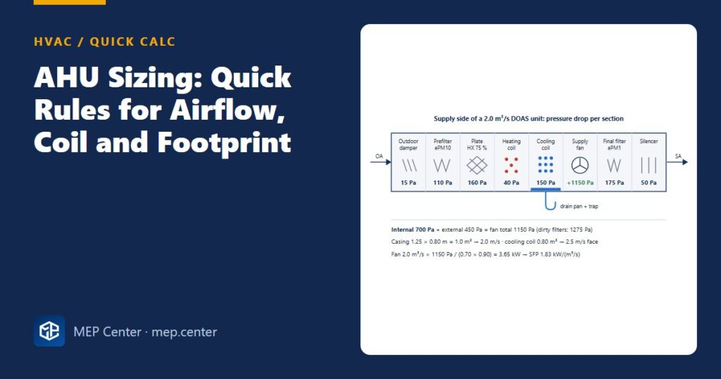
- Casing: 2.0 / 2.0 = 1.0 m² → internal 1.25 m wide × 0.80 m high.
- Cooling coil finned area ≈ 0.80 m² → face velocity 2.0 / 0.80 = 2.5 m/s (at the upper limit; a slightly larger casing would bring it to 2.2 m/s).
- After heat recovery: 34 − 0.75 × (34 − 25) = 27.25 °C, h 63.1 kJ/kg; coil-off h 34.8 kJ/kg. Mass flow ≈ 2.40 kg/s.
- Cooling coil: 2.40 × (63.1 − 34.8) = 67.9 kW (84.7 kW without heat recovery). Water: 67.9 / (4.19 × 6) = 2.70 kg/s. Condensate: 2.40 × (14.0 − 8.62) = 12.9 g/s = 46.5 kg/h.
- Pressure: internal 700 Pa + external 450 Pa = 1150 Pa fan total.
- Fan: 2.0 × 1150 / (0.70 × 0.90) = 3.65 kW electrical → SFP 3.65 / 2.0 = 1.83 kW/(m³/s), class SFP4.
Sanity check: 67.9 kW / 2.0 m³/s ≈ 34 kW per m³/s of outdoor air, a normal figure for a hot, humid design day with heat recovery.
Rule-of-thumb table
| Item | Typical value | Note |
|---|---|---|
| Supply airflow per kW sensible | 83 L/s (300 m³/h) at ΔT 10 K | q = Qs / (1.2 ΔT) |
| Casing velocity | ≈ 2.0 m/s | Lower = bigger unit, less fan energy |
| Cooling coil face velocity | 2.0–2.5 m/s | Above ≈ 2.5–2.8 m/s: carry-over |
| Heating coil face velocity | 2.5–3.0 m/s | 1–2 rows, 20–60 Pa |
| Cooling coil rows / air ΔP | 4–8 rows; 6 rows wet 120–200 Pa | More rows, lower bypass factor |
| Coil water-side ΔP | ≤ 30–50 kPa | Counterflow connection |
| Heat recovery efficiency | Wheel 70–85 %, counterflow plate 75–90 %, run-around 40–60 % | Ecodesign minimum 73 % (run-around 68 %) |
| SFP class (EN 16798-3) | SFP3 ≤ 1250, SFP4 ≤ 2000 W/(m³/s) | Check against local energy rules |
Step 4: footprint and plant room
Unit length depends on the sections you include (heat recovery, humidifier, silencers), so take it from a quick selection or a similar past project. Width and clearances you can fix now:
- Coil withdrawal side: unit width + about 300 mm, so a coil comes out in one piece; 1.0–1.2 m in front of every access door and filter section.
- Back side: 0.6 m minimum, more where valves, pipes and traps sit.
- Plinth: 150–200 mm or more, so the condensate trap fits under the drain connection (see condensate trap design).
- Delivery route: units arrive in sections; check doors, lifts and weights before the plant room is frozen.
For the example, with a casing about 1.35 m wide outside, the plant room needs roughly 0.6 + 1.35 + 1.65 = 3.6 m of width, before ducts and pipes.
Typical values — verify with the edition adopted locally.
HVAC Systems Design — Heating, Cooling & Ventilation
28 modules from heat loss to plant room: boilers, heat pumps, cooling loads, psychrometrics, AHUs and ductwork. The VRF course is included.
Modules 1–3 are free, no account needed · full course €15,00 one-time
FAQ
What face velocity should an AHU cooling coil have?
2.0–2.5 m/s across the finned area. Above about 2.5–2.8 m/s condensate droplets are carried off the fins into the fan and ductwork unless a droplet eliminator is fitted.
How do I estimate AHU airflow from the cooling load?
Use q (L/s) = sensible load (W) / (1.2 × ΔT). At a 10 K supply temperature difference that is about 83 L/s, or 300 m³/h, per kW of sensible load.
How much space does an AHU need around it?
On the coil side, the unit width plus about 300 mm for coil withdrawal and 1.0–1.2 m in front of access doors; 0.6 m at the back; and a 150–200 mm plinth for the condensate trap. Confirm with the manufacturer.