
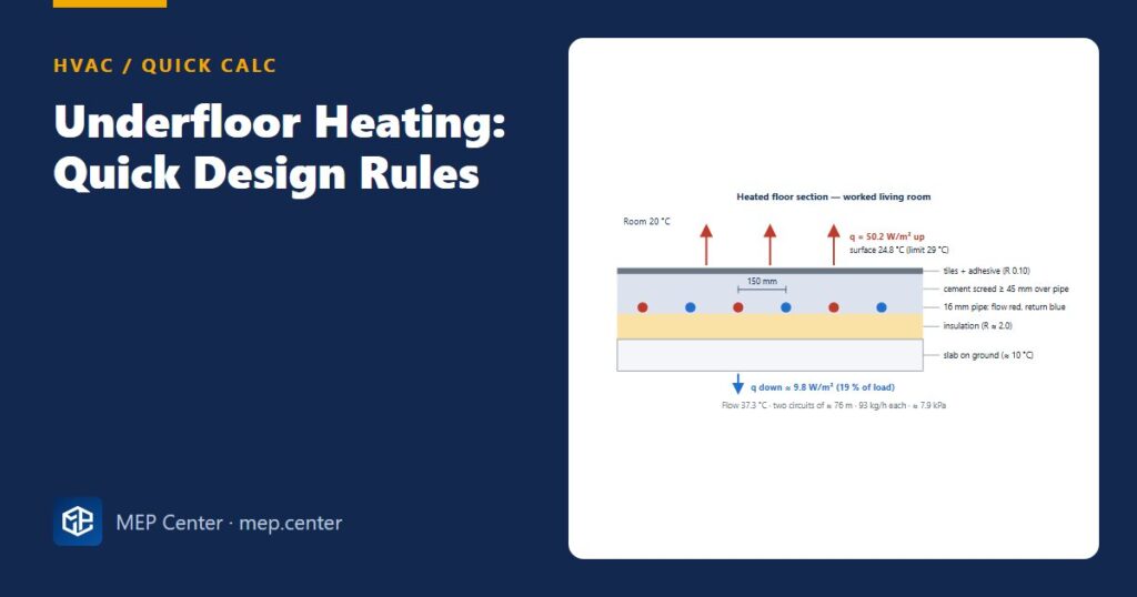
Underfloor heating looks simple on a drawing — a manifold and some loops — but a few numbers decide whether it works: the heat flux per square metre, the surface temperature limit, and the one room that drags the flow temperature of the whole house up. Here is the quick design sequence with a worked room.
The formulas
Heat flux: q = ΦHL / AF (W/m²), with AF excluding fixed furniture, kitchen units and shower trays.
Surface temperature: q = 8.92 × (θF,m − θi)1.1 → Δθ = (q / 8.92)1/1.1. θF,m = mean floor surface temperature, θi = room temperature.
Flow temperature: q = KH × ΔθH → θV = θi + ΔθH + σ/2. KH (W/m²K) comes from the manufacturer’s tested curve for the spacing and floor covering; ΔθH is the log-mean water-to-room difference; σ is the water spread, at most 5 K in the design room.
Pipe length: about 1/spacing metres per m²: 100 mm → 10 m/m², 150 mm → 6.7 m/m², 200 mm → 5 m/m².
Worked example: 18 m² living room
Flux: 904 / 18 = 50.2 W/m² — well below 100 ✓.
Surface: (50.2 / 8.92)0.909 = 4.81 K → 24.8 °C ✓ (limit 29 °C).
Flow temperature: ΔθH = 50.2 / 3.4 = 14.8 K → θV = 20 + 14.8 + 2.5 = 37.3 °C.
Water flow (ground-floor slab, downward losses included, factor 1.195): 18 × 50.2 / (5 × 4 190) × 1.195 = 0.0515 kg/s = 186 kg/h.
Pipe: 18 × 6.7 = 120 m + leads 2 × 8 m = 136 m → too long for one 16 mm loop → two circuits of ≈ 76 m (≈ 60 m in the room + 16 m leads each), 93 kg/h each, ≈ 0.23 m/s, ≈ 87 Pa/m → ≈ 7.9 kPa with fittings ✓.
Sanity check: downward loss ≈ 9.8 W/m² (≈ 176 W, 19 % of the room load) — that is why insulation under the pipes matters.
The worst room sets the flow temperature
All circuits on one manifold get the same water. In the same house the 5 m² bathroom (24 °C, 430 W) needs 86 W/m²: surface 31.9 °C (limit 33 °C ✓), but with 100 mm spacing and KH ≈ 5.44 the flow must be 24 + 15.8 + 2.5 = 42.3 °C — 5 K above the living room. A 150 W towel radiator drops the floor’s share to 56 W/m² and the bathroom’s need to 36.8 °C. The living room then governs and the design flow becomes ≈ 38 °C. On a heat pump that is worth roughly 10–15 % in efficiency.
Rules of thumb
| Item | Typical value |
|---|---|
| Surface limit, occupied zone | 29 °C → ≈ 100 W/m² (room 20 °C) |
| Bathroom limit | θi + 9 K = 33 °C → ≈ 100 W/m² |
| Edge zone (≤ 1 m strip at glazing) | 35 °C → ≈ 175 W/m² |
| Spacing 300 → 150 mm | ≈ +25–45 % output |
| Carpet instead of tiles | ≈ −30–50 % output |
| Circuit length | ≈ 100–120 m (16 mm), 120–150 m (20 mm) |
| Circuit pressure drop | below ≈ 20–25 kPa, balanced at the manifold |
| Manifold size | up to ≈ 10–12 circuits |
| Screed cover | cement ≥ 45 mm, calcium sulphate ≥ 35 mm |
| Screed bays | ≤ 40 m², ≤ 8 m side, ≤ 2:1 |
| Safety limiter on a mixing station | ≈ 50–55 °C |
Room loads come from heat loss calculation step by step. For the heat source see heat pump sizing and the bivalent point; for mixed systems with radiators, radiator sizing correction factors.
Typical values — verify with the edition adopted locally and with the manufacturer’s tested characteristic curves (the KH value above is illustrative).
HVAC Systems Design — Heating, Cooling & Ventilation
28 modules from heat loss to plant room: boilers, heat pumps, cooling loads, psychrometrics, AHUs and ductwork. The VRF course is included.
Modules 1–3 are free, no account needed · full course €15,00 one-time
FAQ
How many watts per square metre can underfloor heating deliver?
About 100 W/m² in occupied areas, where the floor surface may reach 29 °C at a 20 °C room. Edge zones along glazing may reach 35 °C and about 175 W/m².
What flow temperature does underfloor heating need?
Room temperature plus the required water-to-room difference from the system curve plus half the water spread. A well-insulated living room at 50 W/m² needs about 37–38 °C; the worst room on the manifold sets the value for all.
How long can an underfloor heating loop be?
About 100–120 m for 16 mm pipe and 120–150 m for 20 mm, including the leads to the manifold. Longer loops exceed the pressure drop and temperature drop limits, so split the room into several circuits.