
In any building with a booster set or strong mains pressure, the lower floors get more pressure than taps, mixers and flexible hoses are made for. Noise, splashing, dripping valves and burst connectors follow. A properly laid-out pressure reducing valve (PRV) station solves it — and a badly laid-out one fails quietly and nobody can service it.
Step-by-step
- Map the static pressure on every floor. Start from the booster discharge or the maximum mains pressure and add 1 bar for every 10.2 m you go down. Why: this shows which floors exceed the limit and need reducing.
- Define the pressure zones. Each zone covers the floors between the maximum allowed static at its lowest outlet and the minimum flow pressure at its highest outlet; in practice about 30–35 m of height. Why: one PRV per zone is simpler than one per apartment.
- Choose the set pressure. Set pressure = minimum flow pressure at the top outlet of the zone + height from the PRV to that outlet + friction, while checking the lowest outlet stays under the limit. Why: too low starves the top of the zone, too high defeats the purpose.
- Size the PRV for the flow. Take the zone’s probable peak flow and pick the valve from the manufacturer’s flow and fall-off data; the PRV is often one size smaller than the pipe. Why: an oversized PRV hunts and chatters at low flow.
- Check the pressure ratio. If the inlet-to-outlet ratio is high (many manufacturers say above about 3:1), use two PRVs in series or follow the cavitation chart. Why: a big single drop causes cavitation noise and seat wear.
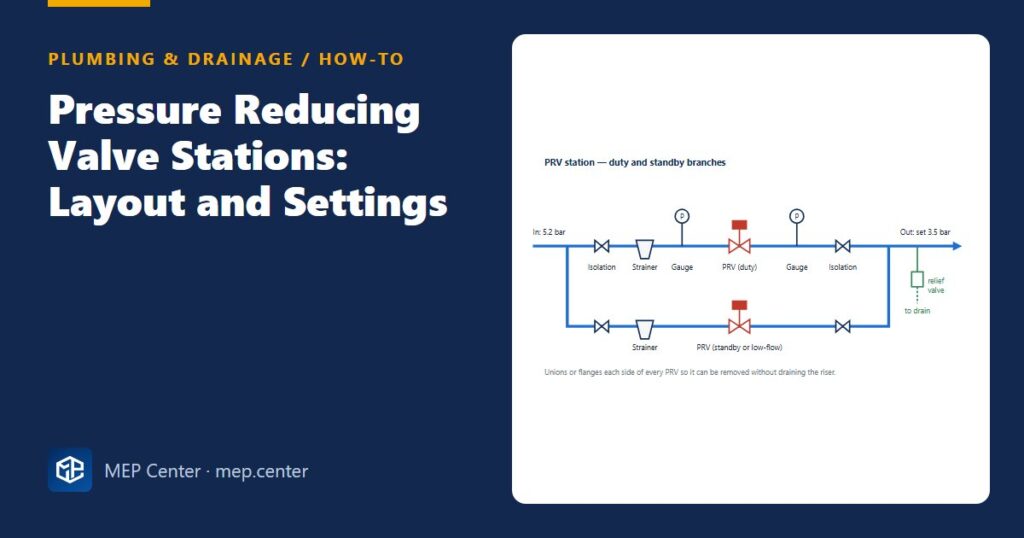
- Lay out the station. Isolation valves both sides, strainer upstream, gauges both sides, unions or flanges to remove the PRV, and a parallel PRV (duty/standby, or a small and a large valve for low and high flows). Why: the strainer protects the seat; the parallel branch keeps water on during service.
- Protect the downstream side. Where a PRV failure could over-pressurise equipment rated below the upstream pressure, add a pressure relief valve downstream piped to a visible drain. Why: PRVs can fail open.
- Place it where it can be serviced. In a riser cupboard or plant room at working height, with a floor drain or tundish nearby, never above a ceiling. Why: strainers need cleaning and PRVs need checking.
- Commission. Set the outlet pressure with flow stopped downstream, then open outlets to design flow and record the fall-off; check that pressure does not creep up overnight. Why: creep means a worn or dirty seat.
Worked example
Situation: the booster set from our booster pump sizing example delivers 55 m of head. The lowest floor outlet (+2 m) sees about 5.2 bar static — above the 5 bar limit. A PRV is placed on the riser at +2 m to feed a low zone covering outlets from +2 m to +11 m.
- Target: at least 1.5 bar flow pressure at the highest outlet of the zone (+11 m).
- Height from PRV to that outlet: 9 m ≈ 0.9 bar. Friction in the zone at design flow: about 0.3 bar.
- Minimum set pressure = 1.5 + 0.9 + 0.3 = 2.7 bar. Choose 3.5 bar to allow for fall-off at flow.
- Lowest outlet static = 3.5 bar (it is at the PRV level) — well under 5 bar.
- Highest outlet at design flow ≈ 3.5 − 0.9 − 0.3 = 2.3 bar (less the PRV’s fall-off) — above the 1.5 bar target.
- Pressure ratio 5.2 / 3.5 ≈ 1.5 → a single stage is fine.
Sanity check: floors above +11 m stay on the unreduced riser; the next floor up at +14 m sees about (55 − 14) / 10.2 ≈ 4.0 bar static, so no further reduction is needed there.
Typical limits
| Item | EN 806-2 practice | IPC practice |
|---|---|---|
| Maximum static at outlets | about 5 bar | 80 psi (about 5.5 bar) — PRV required above |
| Usual set pressure for flats | 3–4 bar | 50–65 psi |
| Two-stage reduction | when the ratio exceeds about 3:1 or the manufacturer’s cavitation chart says so | |
Typical values — verify with the edition adopted locally.
Hot water systems need the same thinking: cold and hot supplies to a mixer should be at similar pressures, so a PRV on the cold feed often protects the water heater too. Thermal expansion of a closed hot water system downstream of a PRV must be absorbed by an expansion vessel — see hot water recirculation and Legionella for the hot side, and common plumbing design mistakes for the slips we see most.
Ready-made drawings and tools for your next project
CAD block libraries, detail drawings and AutoCAD tools made by practising MEP engineers.
FAQ
Where should a pressure reducing valve be installed?
Where the static pressure first exceeds the allowed maximum, typically on the riser branch feeding a low pressure zone, in an accessible riser cupboard or plant room with a drain nearby.
What pressure should a PRV be set to?
High enough to give the minimum flow pressure at the highest outlet of the zone after height and friction losses, and low enough that the lowest outlet stays under the maximum. For flats this is commonly 3 to 4 bar.
Why install two PRVs in parallel?
So the zone stays supplied while one valve is serviced, and so a small valve can handle low night flows smoothly while the larger one opens for peak demand.
Is a strainer necessary before a PRV?
Yes. Debris on the seat is the most common cause of PRV creep and failure, so a cleanable strainer is fitted upstream of every PRV.