
Plan reviewers and insurer engineers see the same sprinkler errors again and again. Most are not exotic. They are basic rules applied to the wrong case, or forgotten under deadline pressure. Here are twelve that get sprinkler submittals sent back, each with what goes wrong and what to do instead.
Classification and design basis
1. Using an old or guessed hazard class
What happens: a car park is designed as Ordinary Hazard Group 1 because “that’s what we always do”. Why it’s rejected: NFPA 13 (2022) puts car parks in OH2, and car stackers in EH2. Storage areas treated as “ordinary” miss the storage chapters entirely. Instead: classify each area against the current edition and write the class and its source on the drawing. See the hazard classification guide.
2. Forgetting the area modifiers
What happens: a dry or double-interlock system is calculated over 139 m² (1500 ft²). Why it’s rejected: these systems need +30 % area (181 m² / 1950 ft²), and a ceiling steeper than 2 in 12 adds another 30 %. The two are cumulative, giving 2535 ft² (236 m²). Instead: list the modifiers in the calculation header. See dry pipe vs preaction.
3. Misusing the quick-response reduction
What happens: the 40 % QR area reduction is taken under a 9 m ceiling, or in an Extra Hazard area. Why it’s rejected: it applies only to wet LH/OH systems with QR sprinklers and ceilings up to 6.1 m (20 ft), on a sliding scale of 40 % at 3 m down to 25 % at 6.1 m, and never below 5 sprinklers. Instead: use the actual maximum ceiling height in the formula 55 − 1.5 × h (ft).
Hydraulics
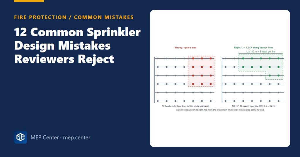
4. A square remote area
What happens: the remote area is drawn as a square, or with its long side across the branch lines. Why it’s rejected: NFPA 13 requires the long side along the branch lines, L ≥ 1.2√A, with fractional sprinklers rounded up. A square puts fewer heads on each branch line and underestimates friction. Instead: for 139 m², L = 1.2 × √139 = 14.2 m along the lines.
5. Under-pressure end sprinkler
What happens: the most remote head is run at whatever the density gives, for example 2 psi. Why it’s rejected: standard spray sprinklers need at least 0.5 bar (7 psi). A K5.6 (K80) head therefore flows at least 56 L/min (14.8 gpm). Instead: take the larger of the density flow and the minimum-pressure flow at the end head.
6. C = 120 on dry or preaction pipe
What happens: every steel pipe is calculated at C = 120. Why it’s rejected: NFPA 13 uses C = 100 for dry and preaction steel, black or galvanised, and C = 120 only for wet and deluge systems. Instead: set C by system type, and use 140 for cement-lined ductile iron and 150 for plastic underground.
7. No hose allowance, or the wrong duration
What happens: the pump and tank are sized for the sprinklers alone. Why it’s rejected: NFPA adds hose: 380 L/min (LH), 950 L/min (OH) or 1900 L/min (EH), for 30 / 60–90 / 90–120 minutes. Instead: add the hose at the right node and size the tank for the total demand × duration.
Layout
8. Spacing and wall distances “near enough”
What happens: OH heads at 3.6 × 3.6 m (13 m²), or 2.5 m from a wall. Why it’s rejected: OH allows a maximum of 12.1 m² and 4.6 m, walls at no more than half the spacing, and at least 1.8 m between heads. Instead: check every room, not only the typical bay. See spacing and location rules.
9. Ducts and beams drawn over sprinklers
What happens: a 1.5 m wide duct runs under a row of ceiling heads. Why it’s rejected: obstructions wider than 1.2 m (4 ft) need sprinklers below them, and the beam rule and three-times rule (3 × D, max 610 mm) govern smaller ones. Instead: run the obstruction check on the coordinated model, not the architectural ceiling plan.
10. Deflectors and storage clearance ignored
What happens: deflectors sit 400 mm below the deck, or storage is stacked to the heads. Why it’s rejected: unobstructed construction allows 25–305 mm (1–12 in), and storage needs 457 mm (18 in) clearance, or 914 mm (36 in) for ESFR. Instead: dimension deflector distances on sections and mark the clearance line on racks.
Installation details
11. Hangers on services, long unsupported ends
What happens: pipe is hung from duct flanges, or the end head is 1.5 m past the last hanger on 1 in pipe. Why it’s rejected: hangers must go to the structure, and the 1 in steel limit is 0.9 m (36 in). Instead: follow hanger spacing and support rules.
12. Valves, alarms and FDC in the wrong place
What happens: the FDC tees in below the main control valve, a vane flow switch sits on a dry riser, or there is no inspector’s test connection. Why it’s rejected: the FDC must enter on the system side of the control valve. Vane switches belong on wet pipe only. Every system needs a main drain sized to the riser (¾, 1¼ or 2 in) and an inspector’s test connection. Instead: draw the riser trim as a detail on every submittal.
Typical values — verify with the edition adopted locally.
For the full method behind mistakes 4–7, work through the step-by-step sprinkler hydraulic calculation.
Fire Protection & Suppression Systems Design (NFPA)
20 narrated modules with animated diagrams, two complete worked projects (DWG + DXF), the Fire Calc Workbook and an online calculator.
Modules 1–3 are free, no account needed · full course €15,00 one-time
FAQ
What is the most common reason sprinkler drawings are rejected?
Wrong design basis: an outdated or guessed hazard class, missing area modifiers such as the 30 % increase for dry systems, or a remote area that does not follow the 1.2√A rule. Spacing and obstruction errors come next.
Which C-factor should I use for dry sprinkler pipe?
NFPA 13 uses C = 100 for steel pipe in dry and preaction systems, black or galvanised. C = 120 applies to wet and deluge steel pipe.
What shape must the remote area be?
A rectangle with its long side parallel to the branch lines, at least 1.2 times the square root of the design area. For 139 m² that is 14.2 m, with fractional sprinklers per line rounded up.
What minimum pressure applies at the end sprinkler?
Typically 0.5 bar (7 psi) for standard spray sprinklers unless the listing says otherwise. A K5.6 (K80) sprinkler at that pressure flows about 56 L/min (14.8 gpm).
More Fire Protection (Sprinklers, NFPA) articles
- Fire Water Tank Sizing: Sprinklers plus Hose Streams
- Clean Agent System Design for Server Rooms (NFPA 2001)
- ESFR Sprinklers: Quick Rules Before You Specify Them
- Kitchen Hood Wet Chemical Systems: Design Basics
- Sprinkler Hazard Classification: LH, OH1, OH2, EH1 and EH2 Explained
- Sprinkler Spacing Rules: Areas, Wall Distances and Obstructions