
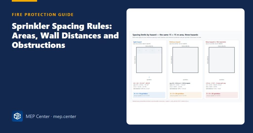
Most sprinkler drawings that come back from review are not rejected for hydraulics. They are rejected for layout: a head too far from a wall, a protection area just over the limit, or a duct nobody checked. The spacing rules in NFPA 13 are simple once you see what they are trying to achieve. This guide gives you the numbers, the reasoning behind them and a worked office layout you can copy.
- Protection area As = S × L, where each side is the larger of the spacing and twice the wall distance.
- Typical maximums for standard spray: LH 20.9 m² (225 ft²), OH 12.1 m² (130 ft²), EH 9.3 m² (100 ft²), and 4.6 m (15 ft) spacing in LH and OH.
- Wall distance is at most half the maximum spacing, 2.3 m (7.5 ft) in LH/OH, and at least 100 mm (4 in).
- Keep sprinklers at least 1.8 m (6 ft) apart, or fit a baffle, so that one head cannot cold-solder the next.
- Obstructions: apply the three-times rule (max 610 mm / 24 in), the beam rule, and put sprinklers below anything wider than 1.2 m (4 ft).
- Check spacing and area together, because each can fail while the other passes.
What the location rules are trying to achieve
Every location rule serves one of three goals:
- Early operation. The sprinkler must sit in the thin hot ceiling jet, close to any possible fire.
- Unobstructed distribution. Once open, its spray must reach the floor across the whole protection area.
- No interference. One operating head must not wet (“cold-solder”) its neighbour and delay it.
Keep these in mind and you can judge situations the rules do not describe exactly. This guide covers standard-spray upright and pendent sprinklers. Sidewall, extended coverage, residential, ESFR and CMSA heads have their own rules and listings.
All values here are typical NFPA 13 (2022) values summarised in our own words. Verify them with the edition adopted locally and with the listing of the sprinkler you use.
Protection area: the S × L method
The protection area of a sprinkler is As = S × L:
- S (along the branch line) is the larger of the distance to the next sprinkler and twice the distance to the end wall.
- L (across the branch lines) is the larger of the distance to the adjacent line and twice the distance to the side wall.
The factor of two stops you hiding a long wall distance behind short head-to-head spacing. A sprinkler 2.1 m from a wall “owns” 4.2 m of spacing on that side. The same As is used again in the hydraulics, where each sprinkler must discharge at least density × As.
Maximum protection area and spacing by hazard
| Hazard (hydraulically calculated) | Max area per sprinkler | Max spacing | Max to wall | Reduced when… |
|---|---|---|---|---|
| Light | 20.9 m² (225 ft²) | 4.6 m (15 ft) | 2.3 m (7.5 ft) | Pipe schedule 18.6 m² (200 ft²); combustible obstructed 15.6 m² (168 ft²); combustible members < 0.9 m (3 ft) apart 12.1 m² (130 ft²) |
| Ordinary (OH1/OH2) | 12.1 m² (130 ft²) | 4.6 m (15 ft) | 2.3 m (7.5 ft) | — |
| Extra and high-piled storage, density ≥ 10.2 mm/min (0.25 gpm/ft²) | 9.3 m² (100 ft²) | 3.7 m (12 ft) | ≈ 1.8 m (6 ft) | EH pipe schedule 8.4 m² (90 ft²) |
Both limits apply at once. In LH, a 4.6 × 4.6 m grid passes on spacing but gives 21.2 m², which is over 20.9 m². In OH, using 4.6 m in one direction forces the other down to 12.1 / 4.6 = 2.6 m. The hazard class comes from the occupancy; see our sprinkler hazard classification guide if you are unsure.
Distances to walls and between sprinklers
| Distance (standard spray, LH/OH) | Typical value |
|---|---|
| Max between sprinklers or branch lines | 4.6 m (15 ft) |
| Max to wall (half the max spacing) | 2.3 m (7.5 ft) |
| Min to wall | 100 mm (4 in), unless listed closer |
| Min between sprinklers | 1.8 m (6 ft), or a baffle |
| Max to any floor point in irregular rooms | 0.75 × max spacing ≈ 3.4 m |
Measure wall distances to the finished wall face, not to the grid line. Where two heads must be closer than 1.8 m, fit a noncombustible baffle midway between them: at least 200 mm (8 in) long and 150 mm (6 in) high, with its top 50–75 mm (2–3 in) above the deflectors. Remember that a full-height glazed screen or a tall shelf unit can act as a wall for distribution.
The small room rule (light hazard only)
In an LH room of up to 74 m² (800 ft²), unobstructed and enclosed, a sprinkler may be up to 2.7 m (9 ft) from one single wall. Every other wall stays at 2.3 m, and the area limit still applies, with As taken as room area / number of heads. Example: a 4.0 × 5.0 m office (20 m²) can take one off-centre head, 2.0 m from each long wall, 2.3 m from one short wall and 2.7 m from the other. A 4.5 × 6.0 m room (27 m²) exceeds 20.9 m² and needs two heads.
Deflector position below the ceiling
The hot ceiling jet is thin, so the deflector must sit inside it:
- Unobstructed construction (smooth ceilings, members more than 2.3 m / 7.5 ft apart, or trusses at least 70 % open): 25–305 mm (1–12 in) below the ceiling.
- Obstructed construction: 25–152 mm (1–6 in) below the members and no more than 559 mm (22 in) below the deck, or in each bay as the construction type allows.
- Concealed and recessed heads: exactly as the listing says. Never extend the cup to “make it fit”.
- Clearance to contents: at least 457 mm (18 in) clear below standard-spray deflectors. Show this line on storeroom drawings.
On sloped ceilings, set the deflectors parallel to the slope, measure spacing along the slope and put a row within 0.9 m (3 ft) vertically of the peak. Above a pitch of 2 in 12 (16.7 %), the hydraulic design area increases by 30 %.
Obstructions: three rules that cover most cases
The three-times rule (small obstructions)
For pipes, conduits, columns and light fittings within 457 mm (18 in) below the deflector, keep the sprinkler at least 3 × D away horizontally, where D is the largest dimension of the obstruction. The required distance never needs to exceed 610 mm (24 in).
If you cannot meet the distance, add a sprinkler on the other side of the obstruction, which is the usual fix for columns, or move the service at coordination stage. Some items are exempt, such as the system’s own small branch piping, so check the exemption list of your edition before relying on one.
The beam rule (continuous obstructions)
For beams, soffits and ducts running along the ceiling, the permitted height of the deflector above the bottom of the beam (B) grows with the horizontal distance to the beam (A). Close to the beam, under about 0.3 m (1 ft), the deflector must be at or below the beam soffit. At about 0.9 m (3 ft), it may be roughly 240 mm (9.5 in) above it, and from about 1.5 m (5 ft), up to 457 mm (18 in). Use the edition’s table for the steps in between. If a beam is too deep, move the head away, lower it within the obstructed-construction limits, or add a head on the other side.
Wide obstructions (more than 1.2 m)
Ducts, cable tray banks, platforms and similar obstructions wider than 1.2 m (4 ft) need sprinklers below them. Add adjacent widths together: two 700 mm ducts with a 100 mm gap act as one 1.5 m obstruction. Where heads below can be wetted from above, use intermediate-level (shielded) sprinklers. Lock these duct widths, including insulation, with the HVAC designer during 3D coordination.
Worked example: light hazard open-plan office, 15 × 24 m
Inputs. An open-plan office of 15.0 × 24.0 m = 360 m² (about 3875 ft²), with a smooth suspended ceiling of 600 × 600 mm tiles and noncombustible construction. Hydraulically calculated wet system with quick-response standard-spray pendent heads. Limits: 20.9 m² per head, 4.6 m spacing, 2.3 m to walls, minimum 0.1 m to walls and 1.8 m between heads.
- Lower bound from area. 360 / 20.9 = 17.2 → at least 18 heads. This is a floor only, because spacing usually governs.
- Along 24 m. 24.0 / 4.6 = 5.2 → 6 heads per line. Uniform spacing 24.0 / 6 = 4.0 m, with 2.0 m to the walls ✓.
- Across 15 m. 15.0 / 4.6 = 3.3 → 4 lines. Spacing 15.0 / 4 = 3.75 m, with 1.875 m to the walls ✓.
- Area. S = max(4.0, 2 × 2.0) = 4.0 m; L = max(3.75, 2 × 1.875) = 3.75 m. As = 15.0 m² ≤ 20.9 ✓.
- Total. 6 × 4 = 24 sprinklers. Five heads along 24 m would need 4.8 m spacing, and three lines across 15 m would need 5.0 m, so 24 is the minimum for a uniform grid.
- Fit to the 600 mm tile grid. Heads must sit in tile centres, so the spacings become multiples of 0.6 m. Along 24 m: 4.2 m (7 tiles), giving 5 × 4.2 = 21.0 m between end heads and 1.5 m to each wall ✓. Across 15 m: 3.6 m (6 tiles), giving 3 × 3.6 = 10.8 m and 2.1 m to each wall ✓.
- Recheck the edge heads. For a head on an outer line, S = max(4.2, 2 × 1.5) = 4.2 m and L = max(3.6, 2 × 2.1) = 4.2 m, so As = 4.2 × 4.2 = 17.6 m² ≤ 20.9 ✓. The doubled wall distance governs.
Hydraulic consequence. At 4.1 mm/min, each outer head must deliver 4.1 × 17.6 = 72 L/min (about 19 gpm at 0.10 gpm/ft² × 190 ft²), against 4.1 × 15.0 = 62 L/min in the uniform grid. The LH design area of 139 m² holds 139 / 15.0 = 9.3 → 10 heads. At the uniform-grid flow of 61.5 L/min, a K80 head needs (61.5 / 80)² = 0.59 bar (8.6 psi), which is above the 0.5 bar (7 psi) minimum ✓. The hydraulic calculation guide takes it from here.
Sanity check. Every wall distance (1.5 m and 2.1 m) is ≤ 2.3 m and ≥ 0.1 m. Every spacing (4.2 m and 3.6 m) is between 1.8 and 4.6 m. The largest protection area, 17.6 m², is below 20.9 m². Grid-fitting is not free: it raised the flow per edge head by about 18 %.
Concealed spaces, shafts and special rooms
NFPA 13 expects sprinklers throughout, including concealed spaces, unless a specific exemption applies. Typical exemptions are noncombustible voids with minimal combustibles and voids above isolated small rooms of up to 5.1 m² (55 ft²). Electrical rooms can be exempt only when they are dedicated, use dry-type equipment only, have a 2-hour enclosure and hold no storage. In elevator pits, a sidewall head goes no more than 0.6 m (2 ft) above the pit floor. Where machine-room sprinklers need power shutdown, the heat detectors sit within about 0.6 m of each head; our smoke and heat detector spacing guide covers the detector side. Mark every concealed space on the drawings as “sprinklered” or “exempt”, with the reason.
Common mistakes
- Checking spacing but not S × L, or the reverse.
- Forgetting the factor of two for wall distances, especially on edge heads after grid-fitting.
- Using 4.6 m between heads and 2.3 m to walls in an OH room, which gives an area well over 12.1 m².
- Laying out without the reflected ceiling plan, then finding lights and diffusers in the sprinkler positions.
- Dropping heads far below deep slabs or beams “to reach the ceiling line”, out of the hot layer.
- Ignoring ducts wider than 1.2 m, especially two ducts side by side.
- Using the small room rule in an OH room, in a room over 74 m², or towards more than one wall.
- Placing heads closer than 1.8 m across a corridor junction or partition without a baffle.
Quick checklist
- Hazard and construction type identified for every area, and the matching spacing row chosen.
- Max spacing, S × L area, max/min wall distance and min head spacing checked for every head.
- Corners of irregular rooms checked against 0.75 × max spacing.
- Deflector distances shown on sections for each ceiling type; 457 mm (18 in) storage clearance marked.
- Three-times rule, beam rule and wide-obstruction (> 1.2 m) checks done in 3D coordination.
- Sloped ceilings: peak row, deflector orientation and +30 % design area noted.
- Concealed spaces, shafts, pits and electrical rooms listed as sprinklered or exempt.
- Largest As per area passed to the hydraulic calculation.
Fire Protection & Suppression Systems Design (NFPA)
20 narrated modules with animated diagrams, two complete worked projects (DWG + DXF), the Fire Calc Workbook and an online calculator.
Modules 1–3 are free, no account needed · full course €15,00 one-time
FAQ
What is the maximum spacing between sprinklers?
For standard-spray upright and pendent sprinklers, it is 4.6 m (15 ft) in light and ordinary hazard and 3.7 m (12 ft) in extra hazard with densities of 10.2 mm/min (0.25 gpm/ft²) or more. The protection-area limit must be met at the same time.
How far can a sprinkler be from a wall?
No more than half the maximum spacing, which is 2.3 m (7.5 ft) in light and ordinary hazard, and at least 100 mm (4 in). In small light hazard rooms, one single wall may be up to 2.7 m (9 ft) away.
What is the minimum distance between two sprinklers?
1.8 m (6 ft) for standard-spray sprinklers, so that one operating head does not cool its neighbour. If they must be closer, fit a noncombustible baffle midway between them.
How do I calculate the protection area of a sprinkler?
Multiply S by L. Each is the larger of the distance to the next sprinkler or line and twice the distance to the wall. For example, 3.6 m spacing with 2.1 m to the wall gives S = 4.2 m.
When do I need sprinklers under a duct?
When the duct, or a group of adjacent obstructions, is wider than 1.2 m (4 ft). Add the widths of side-by-side ducts and include the insulation.
More Fire Protection (Sprinklers, NFPA) articles
- Sprinkler Hazard Classification: LH, OH1, OH2, EH1 and EH2 Explained
- Fire Hydrant Connection to the Fire Main (NFPA 24 Practice)
- Fire Department Connection (FDC): Location and Arrangement
- Choosing the Sprinkler K-Factor
- Fire Pump Room Design Checklist
- Dry Pipe vs Preaction: Choosing the Sprinkler System Type