
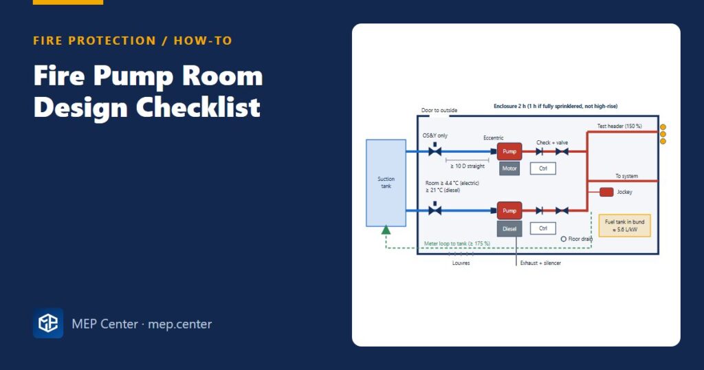
Most fire pump problems are not pump problems. They are room problems: a butterfly valve on the suction, no space to pull the motor, a diesel room that drops to 5 °C in January, or a test header discharging into a car park. Use this checklist when you lay out a fire pump room, and again before the drawings go to review.
The checklist, step by step
- Enclosure: separate the room with 2-hour construction in high-rise buildings and buildings that are not fully sprinklered, and 1-hour where a non-high-rise building is fully sprinklered. Why: the pump must keep running during the fire it is fighting.
- Access: give a door directly to outside, or a protected passage to it. Why: firefighters and the service technician must reach the controller during a fire.
- Flooding: provide a floor drain, raise the pump bases on plinths, and keep no water or drainage pipes above controllers. Why: a pump room in a basement is also the lowest point for every leak and every test discharge.
- Temperature: keep the room at 4.4 °C (40 °F) minimum for electric pumps and 21 °C (70 °F) for diesel, unless the engine maker accepts lower with jacket heaters. Why: cold diesels fail to start, and water-filled casings freeze.
- Suction valve: within 15 m (50 ft) of the suction flange, use only a listed OS&Y gate valve and never a butterfly. Why: even an open butterfly disc distorts the flow entering the impeller.
- Straight suction: an elbow whose plane is parallel to the shaft of a split-case pump must be at least 10 pipe diameters from the flange. Check valves and backflow preventers on the suction also stay at least 10 diameters away. Why: uneven flow loads one side of a double-suction impeller.
- Reducer: use an eccentric reducer with the flat side on top, never a concentric one. Why: a concentric reducer traps an air pocket at the impeller eye.
- Suction size: keep velocity at 4.6 m/s (15 ft/s) or less at 150 % of rated flow, and suction pressure at least 0 bar gauge at 150 %. About −0.2 bar is allowed for a tank at or above the pump. Why: these limits keep the pump out of cavitation at the overload point.
- Discharge train: fit, in order, a gauge, a check valve and an indicating control valve (a butterfly with tamper switch is acceptable here). Connect the controller’s pressure sensing line between the check valve and the control valve. Fit a circulation relief valve on each pump. Why: this lets the pump be isolated and tested, stops backflow, and prevents overheating at churn.
- Test facilities: provide a test header through an outside wall sized for 150 % flow, with a drain and an inside control valve. Add a flow meter loop back to the tank rated for at least 175 % of rated flow. Why: NFPA 25 tests at churn, 100 % and 150 %, and the water needs somewhere safe to go.
- Controllers: place them listed for fire pump service, within sight of their driver, facing it and protected from spray. The electric supply must be reliable, with protection that carries locked-rotor current. Voltage drop is limited to 15 % at the controller on starting and 5 % at the motor at 115 % of full-load current. Why: a fire pump circuit is designed not to trip.
- Diesel extras: size the fuel tank at about 5.6 L/kW (1 gal/hp + 5 % expansion + 5 % sump), inside a bund with a level gauge and low-fuel alarm. Pipe the exhaust outside with a silencer and flexible connector. Provide combustion and cooling air openings, and two battery sets. Why: the engine must run unattended for the full duration.
- Jockey pump: make it smaller than one sprinkler’s flow, about 1 % of the main pump flow. Step the settings down: jockey stop, then jockey start 0.7 bar (10 psi) lower, then main pump start 0.35 bar (5 psi) lower again. Why: a single open sprinkler must still start the main pump.
- Maintenance space: leave clearance to lift the split-case top casing and pull the motor. Provide a lifting beam or eye, electrical working space at controller doors, lighting and emergency lighting, and sprinklers in the room. Why: a pump that cannot be serviced will not be.
Sizes for a common case: a 2839 L/min (750 gpm) pump
Typical NFPA 20 table values for 750 gpm are an 8 in (200 mm) suction, a 6 in (150 mm) discharge, and a test header with 3 × 2½ in hose valves on 6 in pipe.
Suction velocity at 150 % flow (1125 gpm): v = 0.4085 × 1125 ÷ 7.981² = 7.2 ft/s (2.2 m/s), well under 15 ft/s.
Straight length before the pump: 10 × 8 in = 80 in ≈ 2.0 m of straight suction pipe in the room. Draw it before you fix the pump positions.
Meter loop: at least 1.75 × 750 = 1313 gpm (4970 L/min).
Typical values — verify with the edition adopted locally.
For the pump selection itself (rated point, curve checks, motor power, relief valves), see fire pump sizing to NFPA 20. The demand it serves comes from the sprinkler hydraulic calculation or, in taller buildings, from the standpipe demand in standpipe classes explained.
Fire Protection & Suppression Systems Design (NFPA)
20 narrated modules with animated diagrams, two complete worked projects (DWG + DXF), the Fire Calc Workbook and an online calculator.
Modules 1–3 are free, no account needed · full course €15,00 one-time
FAQ
What fire rating does a fire pump room need?
Typically 2 hours in high-rise buildings and in buildings that are not fully sprinklered, and 1 hour in a fully sprinklered building that is not a high-rise. Local codes may ask for more.
Can I use a butterfly valve on the fire pump suction?
No. Within 15 m (50 ft) of the suction flange only a listed OS&Y gate valve is permitted. A butterfly valve is acceptable on the discharge side with a tamper switch.
What is the minimum temperature in a fire pump room?
Typically 4.4 °C (40 °F) for electric pump rooms and 21 °C (70 °F) for diesel pump rooms, unless the engine manufacturer allows a lower value with jacket heaters.
How big should the diesel fuel tank be?
About 1 gallon per engine horsepower plus 5 % for expansion and 5 % for the sump. That is roughly 5.6 litres per kW of engine power.
More Fire Protection (Sprinklers, NFPA) articles
- Clean Agent System Design for Server Rooms (NFPA 2001)
- Fire Hydrant Connection to the Fire Main (NFPA 24 Practice)
- Fire Department Connection (FDC): Location and Arrangement
- 12 Common Sprinkler Design Mistakes Reviewers Reject
- EN 12845 vs NFPA 13: Key Differences for Designers
- Sprinkler Hydraulic Calculation: A Step-by-Step Worked Example