
A refrigerant gas line at 5 °C running through a warm ceiling void is a cold surface in humid air. If the insulation is too thin, crushed at a clamp or open at a seam, water forms on the copper, soaks the insulation and drips through the ceiling — usually months after handover.
The formula
Heat gain per metre of insulated pipe:
q = (Ta − Tp) / [ ln(D2/D1) / (2π·λ) + 1 / (h·π·D2) ] (W/m)
Outer surface temperature: Ts = Ta − q / (h·π·D2). Condition: Ts ≥ Tdew + about 1 K.
- Ta — air temperature around the pipe (°C); Tp — pipe temperature (°C), take about 5 °C for a gas line in cooling as a safe value.
- D1 — pipe outside diameter (m); D2 = D1 + 2 × thickness (m).
- λ — insulation conductivity, typically 0.035–0.040 W/m·K for closed-cell elastomeric foam (0.036 used below).
- h — outer surface coefficient, about 8 W/m²K for a matt surface in still air; shiny cladding is lower and needs more thickness.
- Tdew — dew point of the surrounding air, from the psychrometric chart or the Magnus formula.
Worked example
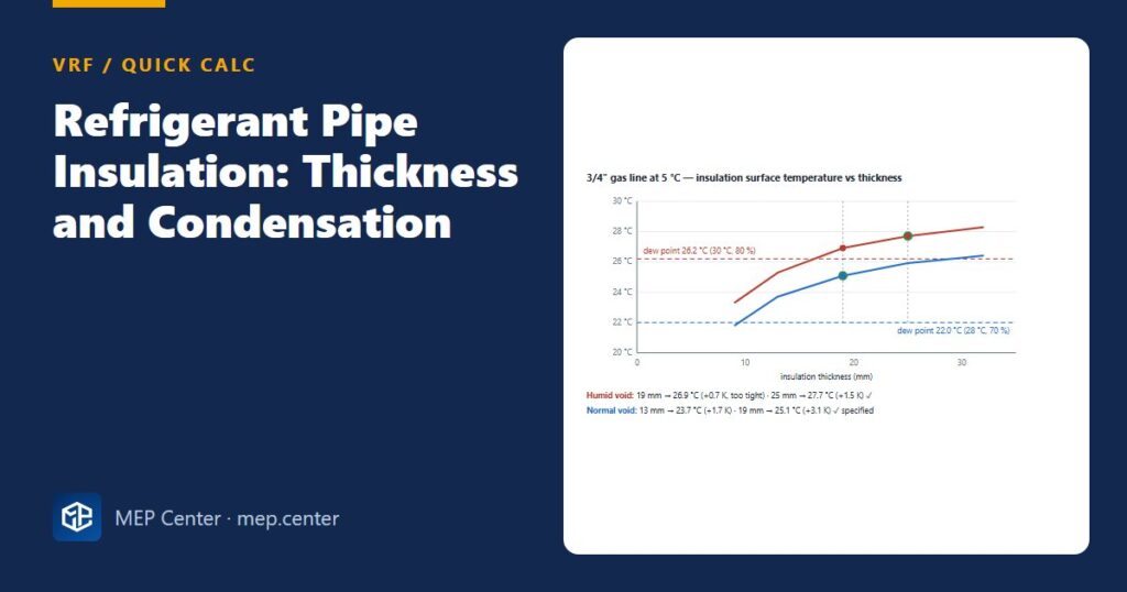
3/4″ gas line (D1 = 19.05 mm) at 5 °C in a humid ceiling void at 30 °C, 80 % RH. Dew point ≈ 26.2 °C.
Try 19 mm: D2 = 19.05 + 38 = 57.05 mm. Insulation resistance ln(57.05/19.05) / (2π × 0.036) = 1.097 / 0.2262 = 4.85 m·K/W. Surface resistance 1 / (8 × π × 0.05705) = 0.70 m·K/W. q = (30 − 5) / 5.55 = 4.51 W/m. Ts = 30 − 4.51 × 0.70 = 26.9 °C → only 0.7 K above the dew point. Too tight.
Try 25 mm: D2 = 69.05 mm. 1.288 / 0.2262 = 5.69 + 1 / (8 × π × 0.06905) = 0.58 → 6.27 m·K/W. q = 25 / 6.27 = 3.99 W/m. Ts = 30 − 3.99 × 0.58 = 27.7 °C → 1.5 K margin ✓.
Same pipe in a normal void (28 °C, 70 % RH, dew point 22.0 °C): 19 mm gives Ts ≈ 25.1 °C, a 3.1 K margin ✓.
Result: 19 mm normal, 25 mm humid — the same as the rule-of-thumb table below. The calculation confirms the table; it should never be used to go thinner than it.
Rule-of-thumb thickness
| Pipe OD | Normal ceiling voids (RH up to about 70–80 %) | Humid voids, unconditioned plant spaces, coastal or hot-humid climates |
|---|---|---|
| Up to 5/8″ | 13 mm | 19 mm |
| 3/4″ – 1 5/8″ | 19 mm | 25 mm (or more, by condensation calculation) |
Typical values — verify with the edition adopted locally, the selected manufacturer and the local energy regulation.
Where the surrounding dew point is high — kitchens, laundries, unventilated roof voids — calculate instead of relying on the table.
Rules that matter more than the millimetres
- Both lines, separately. In cooling the gas line is cold; in heating it carries hot gas up to about 100–120 °C, and the liquid line can be cold or warm depending on mode. Never wrap gas and liquid together.
- Temperature rating at least 120 °C, never below 100 °C, because of the hot gas in heating.
- Seal every seam and joint with the manufacturer’s adhesive, including branch joints and flare connections. One open joint becomes a condensation and corrosion point.
- Support over the insulation with clamps that have a load-bearing insert, so the insulation is not crushed and no metal touches the cold pipe.
- Protect outdoor runs against UV with cladding or coating.
- Fire stopping through rated walls and slabs uses a tested system for insulated copper pipes, installed exactly as tested.
For the pipe sizes these thicknesses go on, see VRF refrigerant piping design; branch joints use the kit shells described in VRF branch kit selection; and the condensate drains running alongside need their own insulation, covered in VRF condensate drainage design. To read the dew point, use the psychrometric chart guide.
VRF / VRV System Design
From room loads to a buildable VRF drawing set: unit selection, connection ratio, refrigerant piping, EN 378 checks and worked projects.
Modules 1–3 are free, no account needed · full course €10,00 one-time
FAQ
What thickness of insulation do refrigerant pipes need?
Typically 13 mm up to 5/8″ and 19 mm for 3/4″ to 1 5/8″ in normal ceiling voids, and 19 mm and 25 mm in humid spaces or hot-humid climates. Verify with the manufacturer and the local energy regulation.
Do both refrigerant lines need insulation?
Yes. Insulate the gas and the liquid lines separately along their whole length, because either can be cold or hot depending on the operating mode.
How do I check refrigerant pipe insulation against condensation?
Calculate the outer surface temperature of the insulation from the pipe and air temperatures, the insulation conductivity and the surface coefficient, and keep it about 1 K or more above the dew point of the surrounding air.