
Most VRF complaints — offices at 27 °C in July, refrigerant alarms nobody planned for, ceilings stained by condensate — trace back to a handful of design decisions. None of them is exotic. Here are the ten we see most often in drawings we review, with what to do instead.
1. Using the 130 % connection ratio as a sizing method
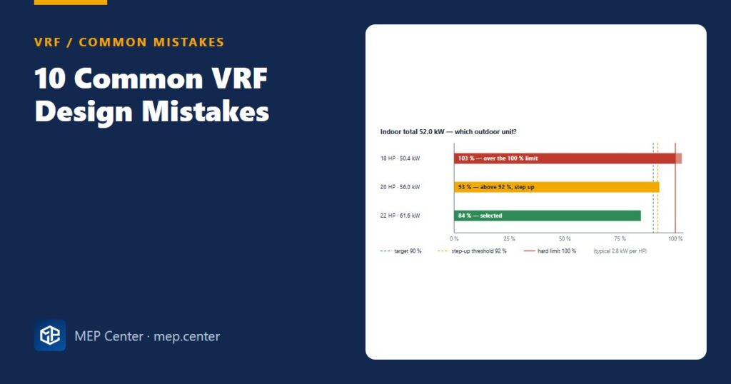
What people do: connect up to the catalogue maximum because “diversity will cover it”. Why it is wrong: the ratio is a compatibility limit, not a capacity check; on a hot afternoon with every room busy, the outdoor unit simply runs out. Instead: our house rule — indoor total never above 100 % of outdoor capacity, target about 90 %, step up one outdoor size when the ratio rounds above 92 %.
2. No capacity corrections
What people do: compare nominal outdoor capacity with the load. Why it is wrong: nominal capacity is at rating conditions. At 46 °C outdoor a typical correction is about 0.88, a 90 m equivalent pipe run about 0.91, and indoor wet bulb below 19 °C reduces capacity further. Instead: multiply all factors and check the corrected capacity against the block load.
3. Combining very different outdoor modules
What people do: reach 44 HP with 30 + 14 HP. Why it is wrong: unequal modules share load and oil badly and give uneven run hours. Instead: modules equal or at most one size step apart (for example 22 + 22 or 20 + 22 HP).
4. Indoor units sized by rule of thumb
What people do: pick units from W/m² and round up “to be safe”. Why it is wrong: oversized units short-cycle, dehumidify poorly and inflate the connection ratio and refrigerant charge. Instead: select from room loads; keep oversize within about 15–20 % unless justified.
5. Pipes and joints sized on the wrong capacity
What people do: size branches on the outdoor capacity, or the main on the indoor total. Instead: main pipe and first branch on the outdoor unit capacity; every other branch and joint on the downstream indoor total — see VRF branch kit selection.
6. Breaking length limits
What people do: check only total pipe length. Why it is wrong: the limits that bite are equivalent length to the farthest unit (above about 90 m the gas main typically goes up one size), the length after the first branch (typically 40 m, up to 90 m with conditions) and height differences. Instead: check the two or three longest routes, including 0.5 m per joint and 1.0 m per header.
7. Skipping the refrigerant check for small rooms
What people do: discover at the end that a 24 kg system serves a 9 m² store room. Why it is wrong: if the whole charge leaks into that room, 24 kg ÷ (3 × 3 × 2.7 = 24.3 m³) ≈ 0.99 kg/m³, more than twice the EN 378 practical limit of 0.44 kg/m³ for R410A. Instead: compute the minimum room volume (charge ÷ 0.44) early and move small rooms to another system or add the required safety measures.
8. Condensate drains without a fall budget
What people do: draw drains as single lines with no levels. Why it is wrong: a continuous fall of at least 1 % consumes real ceiling space — 30 m at 1 % is 300 mm. Instead: check falls, beams and the arrival level at the riser for every collector before the ceiling height is frozen.
9. Treating VRF as ventilation
What people do: assume indoor units provide fresh air. Why it is wrong: they recirculate room air only. Instead: design a separate outdoor air system (heat recovery ventilation or treated fresh air) and account for its load.
10. Outdoor units boxed in
What people do: place outdoor units in a pit, behind solid screens or under a canopy. Why it is wrong: discharge air recirculates, coil inlet temperature rises and capacity drops exactly when you need it. Instead: respect manufacturer clearances, use discharge ducts or louvres with the free area they require, and remember the electrical data changes with every outdoor size change.
Typical values — verify with the edition adopted locally and with the selected manufacturer.
For the full method behind mistakes 1–3, read VRF outdoor unit selection and connection ratio; for 6, VRF refrigerant piping design; for 7, the VRF refrigerant leak safety check.
VRF / VRV System Design
From room loads to a buildable VRF drawing set: unit selection, connection ratio, refrigerant piping, EN 378 checks and worked projects.
Modules 1–3 are free, no account needed · full course €10,00 one-time
FAQ
What connection ratio should I use for VRF design?
Manufacturers typically allow 50–130 %, but in normal comfort projects we keep the indoor total at or below 100 % of the outdoor capacity, aim for about 90 % and step up one outdoor size when the ratio rounds above 92 %.
Why does a VRF system underperform in summer even though the ratio was allowed?
Usually because nominal capacity was compared with the load without corrections for high outdoor temperature, long pipe runs and indoor conditions, often combined with a connection ratio above 100 %.
When do I need to check refrigerant concentration for a VRF system?
Always, at early design stage. Divide the system charge by the room volume of the smallest occupied room it serves; for R410A under EN 378 the practical limit is 0.44 kg/m³.