
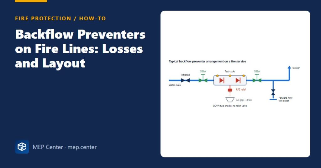
A backflow preventer on the fire service is easy to forget in the hydraulic calculation and expensive to discover at commissioning. It can take 8–12 psi out of the supply at sprinkler flow, and that is often the difference between “the city main is enough” and “we need a fire pump”. Here is how to select it, lay it out and put its loss in the calculation.
Step by step
- Confirm the required assembly type with the water authority. DCVA for lower hazard (plain water, no additives); RPZ for higher hazard (antifreeze loops, FDC fed from a non-potable source, chemicals). Detector versions add a bypass meter to catch leaks or unauthorised use. Why: the authority’s cross-connection rules decide this, not the sprinkler standard.
- Get the design flow from the hydraulic calculation. Use the total flow passing the assembly: sprinkler demand plus any inside hose taken through it. Why: the loss depends strongly on flow.
- Select the size and read the loss at that flow from the manufacturer’s curve. Do not use a generic figure. Many assemblies lose several psi even at low flow because of the check valve springs. Why: the curve is not linear, and two sizes can differ by several psi at the same flow.
- Add the loss to the hydraulic calculation at the connection point, then compare with the supply curve and your safety margin. Why: this is where a gravity or city supply often stops being enough.
- Lay out the assembly with supervised isolation valves both sides. Use listed indicating valves (OS&Y type), supervised like any other control valve. Why: a closed valve in front of the assembly shuts off the whole system.
- Give the RPZ somewhere to discharge. The relief valve dumps water during pressure fluctuations; provide an air gap and a drain sized for full relief flow. Why: an RPZ in a basement with a floor gully floods the room.
- Protect from frost and allow access. Heated room or insulated, heated enclosure; test cocks reachable without ladders. Why: the assembly must be tested every year.
- Provide a forward-flow test connection downstream. A test header or hose outlets that can pass the system demand flow. Why: NFPA 13 requires a means to test the assembly at system demand, and NFPA 25 repeats the forward-flow test yearly.
Worked example: does the city main still work?
Hydraulic calculation at the connection point, without backflow: 415.8 gpm (1574 L/min) at 48.7 psi (3.36 bar).
City main at that flow (from the flow test supply curve): 66 psi (4.55 bar). Design margin used: 10 psi (0.7 bar).
1. With a DCVA losing 6 psi at 415.8 gpm (manufacturer curve): 48.7 + 6 = 54.7 psi (3.77 bar). Margin 66 − 54.7 = 11.3 psi (0.78 bar) ✔
2. With an RPZ losing 12 psi at the same flow: 48.7 + 12 = 60.7 psi (4.19 bar). Margin 66 − 60.7 = 5.3 psi (0.37 bar) ✗
3. Options for the RPZ case: a larger assembly with a flatter curve, larger underground pipe, or a fire pump.
Sanity check: the only change between the two cases is 6 psi of backflow loss, yet it turns a pass into a fail.
Typical values — DCVA ≈ 3–8 psi (0.2–0.55 bar) and RPZ ≈ 8–15 psi (0.55–1.0 bar) are indicative ranges only. Always use the manufacturer’s curve, and verify requirements with the edition adopted locally and the water authority.
Common slips
- Adding a backflow preventer to an existing system without recalculating. The available pressure drops; the system must be checked again.
- Using the loss at rated flow instead of at demand flow. Read the curve at your actual flow.
- No forward-flow test connection. Without it the assembly cannot be tested at system demand, and the annual test turns into a pipe modification.
- RPZ in a pit. Many authorities do not accept RPZ assemblies below grade because the relief port could be submerged.
The friction and supply side of the calculation are covered in sprinkler hydraulic calculation step by step; if the margin fails, continue with fire pump sizing. The underground side is in fire hydrant connection to the fire main.
Fire Protection & Suppression Systems Design (NFPA)
20 narrated modules with animated diagrams, two complete worked projects (DWG + DXF), the Fire Calc Workbook and an online calculator.
Modules 1–3 are free, no account needed · full course €15,00 one-time
FAQ
What is the pressure loss of a backflow preventer on a sprinkler system?
Typically about 3–8 psi (0.2–0.55 bar) for a double check assembly and 8–15 psi (0.55–1.0 bar) for a reduced pressure zone assembly at design flow. The real value must be read from the manufacturer’s curve for the selected size at your demand flow.
DCVA or RPZ for a fire sprinkler line?
The water authority decides. A DCVA is common for plain water systems; an RPZ is usually required where antifreeze, chemicals or a non-potable source such as an FDC fed from open water could contaminate the supply.
Why does a backflow preventer need a forward-flow test?
Because a check valve that opens poorly can restrict flow without anyone noticing. NFPA 13 requires a means to test the assembly at system demand flow, and NFPA 25 requires the forward-flow test to be repeated yearly.
Can an RPZ be installed in a valve pit?
Many water authorities do not allow it, because the relief port could be flooded and become a cross-connection. Install it above ground in a heated room or a heated, drained enclosure.
More Fire Protection (Sprinklers, NFPA) articles
- Fire Water Tank Sizing: Sprinklers plus Hose Streams
- Wet Riser vs Dry Riser: Which Building Needs Which
- Fire Department Connection (FDC): Location and Arrangement
- Fire Pump Room Design Checklist
- Sprinkler Hydraulic Calculation: A Step-by-Step Worked Example
- Fire Pump Sizing to NFPA 20: Rated Point, Curve Checks and Jockey