
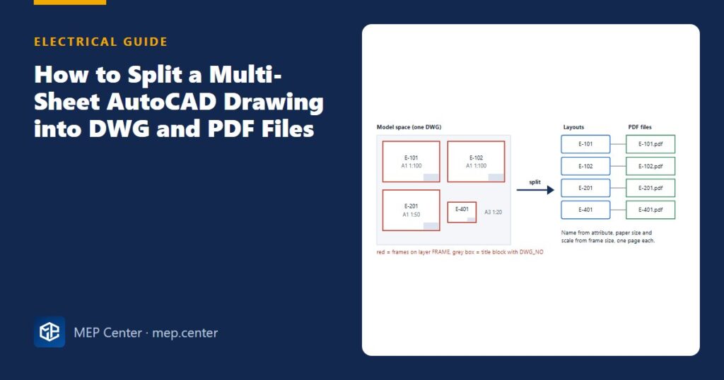
A typical MEP drawing set has 20–60 sheets drawn in one AutoCAD model space, each with its own title block. Getting them out as separate, correctly named PDFs (and layouts in the DWG) is a repetitive job that eats an afternoon before every submission — and the sheet names still get mistyped.
This guide shows how to prepare a multi-sheet model space so the split is reliable, how to check scales and paper sizes from the frame itself, and how to automate the whole run, with a walkthrough of a real-size 24-sheet electrical set.
- Everything automation needs is already in the drawing: the title-block frame gives extents and paper size, the drawing-number attribute gives the file name.
- Put every title-block frame on one dedicated layer (for example FRAME) and nothing else on that layer.
- Scale = frame width in drawing units ÷ paper width in mm. An A1 frame 84 100 units wide is a 1:100 sheet.
- Fill the drawing-number attribute on every title block; an empty attribute means an unnamed PDF.
- Check the output count against the frame count and spot-check two or three page sizes before you send anything.
- Once the model is prepared, a revision is “fix the model, run again, overwrite the PDFs”.
The manual way (and why it hurts)
- Create a layout per sheet and a viewport fitted to the title-block frame.
- Set the viewport scale and lock it.
- Assign a page setup with the right paper size, orientation and plot style.
- Plot each layout to PDF (or batch it with Publish once the layouts exist).
- Rename every PDF to match the drawing number in the title block.
- Repeat steps 4–5 after every revision, and steps 1–3 for every new sheet.
At three to five minutes per sheet, a 40-sheet set costs two to three hours per issue. Three issues before approval and you have spent a working day clicking — and that is before someone notices that E-107.pdf actually contains sheet E-108.
What the drawing already knows
A title-block frame is not just a rectangle. If it is inserted as a block at a known scale, it tells you three things without asking anyone:
- Sheet extents — the frame’s bounding box is exactly the area to plot.
- Paper size and scale — the frame’s width and height in drawing units, divided by the scale, give the paper size in millimetres (and vice versa).
- Sheet name — the drawing-number attribute (for example DWG_NO = E-101) is the file name and the layout name.
Preparing the drawing
Frames
- Use one title-block block per paper size, drawn at 1:1 in millimetres (an A1 frame block is 841 × 594), and insert it at the sheet’s scale factor (×100 for 1:100).
- Put all frames on one layer, for example FRAME, and keep everything else off that layer — a stray rectangle on FRAME becomes a stray sheet.
- Do not explode frames. An exploded frame loses its attributes, so the sheet has no name.
- Keep frames from overlapping. Overlaps plot the neighbour’s edge into your sheet.
Attributes
- Fill the drawing number on every title block and keep the format consistent (E-101, not E101 on one and E-101 on another).
- Characters that are illegal in file names (/ \ : * ? ” < > |) should not appear in the drawing number.
- Revision letters belong in a separate attribute if you want them in the file name (E-101_B.pdf).
Scales and plotting
- Keep sheets at a small number of standard scales where possible; mixed scales are fine but harder to check.
- Annotation must be sized for the scale: 2.5 mm text on paper is 250 units at 1:100 and 125 units at 1:50.
- Decide the plot style (monochrome or colour) and lineweights once, for the whole set.
Automating the split
Because the frames carry all the information, the split can be fully automatic. Our PAFTA sheet splitter reads the frames on a chosen layer, creates one layout per frame with the correct paper size and scale, writes the sheet name from the attribute, and plots vector PDFs (or PNG raster if you prefer). Long sheets beyond the roll width are plotted in parts and merged into one long page. The result is one DWG with layouts, one PDF per sheet named by drawing number, and a log of what was done; empty drawing-number attributes are reported rather than guessed.
PAFTA works with full AutoCAD 2018 or later (not LT).
Worked example: a 24-sheet electrical set
Inputs — one DWG, drawing units millimetres, title-block frames on layer FRAME, attribute DWG_NO on every title block.
| Sheets | Content | Paper | Scale | Frame size in model (units) | Count |
|---|---|---|---|---|---|
| E-101 … E-112 | Power and lighting plans, 6 floors | A1 841 × 594 | 1:100 | 84 100 × 59 400 | 12 |
| E-201 … E-206 | Plant room enlargements | A1 841 × 594 | 1:50 | 42 050 × 29 700 | 6 |
| E-301 … E-304 | Risers and single-line diagrams | A0 1189 × 841 | 1:100 | 118 900 × 84 100 | 4 |
| E-401, E-402 | Typical details | A3 420 × 297 | 1:20 | 8 400 × 5 940 | 2 |
Step 1 — count the frames. Isolate layer FRAME and select all frame blocks: the count must be 12 + 6 + 4 + 2 = 24. Anything else on the layer is either a missing sheet or a stray object.
Step 2 — check each scale from its frame. Scale = frame width ÷ paper width:
84 100 ÷ 841 = 100 → 1:100 ✓
42 050 ÷ 841 = 50 → 1:50 ✓
118 900 ÷ 1189 = 100 → 1:100 ✓
8 400 ÷ 420 = 20 → 1:20 ✓
A frame that gives a different number from its title block (say 84 100 ÷ 841 = 100 on a sheet labelled 1:50) means the title block says one scale and the drawing another — fix it now.
Step 3 — check the attributes. List DWG_NO for all 24 blocks: no blanks, no duplicates, one format. A duplicate (two E-105s) would overwrite one PDF with the other.
Step 4 — run the split. Choose layer FRAME, attribute DWG_NO, output folder, vector PDF.
Step 5 — verify the output. The folder must hold 24 PDFs, E-101.pdf … E-402.pdf. Open one sheet of each type: E-101 should be an 841 × 594 mm page, E-301 1189 × 841 mm, E-401 420 × 297 mm. Measure one known dimension on E-201 with the PDF viewer’s measuring tool: a 5 m plant room wall should measure 100 mm on paper (5000 ÷ 50).
Result and sanity check — 24 layouts and 24 named PDFs, matching the frame count and the sheet register. Time per issue: done by hand at about 4 minutes a sheet, 24 × 4 = 96 minutes, or almost 5 hours over three issues; with a prepared model, each re-issue is a single run plus the checks in step 5.
Revisions without the pain
Once the model is set up this way, a revision is three steps: fix the model, run the split again, overwrite the PDFs. Keep the drawing-number attribute stable between revisions and put the revision letter in its own attribute, so file names and the transmittal stay in step.
The same principle — one source, everything else generated from it — is what keeps electrical deliverables consistent. Cable sizes on the plans should come from the same list as the schedules (see cable sizing for voltage drop), and phase letters on the single-line diagram from the same list as the board schedule (see phase balancing in panel schedules).
Common mistakes
- Frames on the same layer as other rectangles (room outlines, viewports), producing extra “sheets”.
- Exploded or copied-and-scaled frames that lost their attributes, giving unnamed PDFs.
- Duplicate drawing numbers, so one PDF silently overwrites another.
- Scale in the title block not matching the frame’s insertion scale.
- Overlapping frames, so the neighbour’s border or text appears on the edge of a sheet.
- Annotation sized for 1:100 on a 1:50 sheet (text twice as large as the others).
- Sending the set without checking the PDF count and a few page sizes.
Quick checklist
- All frames are blocks on one dedicated layer; nothing else on it.
- Frame count equals the number of sheets in the register.
- Frame width ÷ paper width gives the scale written in the title block.
- Drawing-number attribute filled, unique and file-name safe on every sheet.
- One plot style and lineweight setting for the whole set.
- Output folder holds exactly one PDF per sheet, spot-checked for size and scale.
Electrical Power Systems Design for Buildings
35 modules from the MV connection to the socket: transformers, short circuit, protection and selectivity, cable sizing, boards, generators, earthing, surge and lightning protection. Includes 50 % off TEKHAT.
Modules 1–3 are free, no account needed · full course €15,00 one-time
FAQ
Can AutoCAD split one model space into several PDFs by itself?
AutoCAD can batch-plot existing layouts with its Publish command, but someone still has to create a layout, viewport and page setup for every sheet and rename the files. A frame-based tool automates the layout creation and naming as well.
How do I find the scale of a sheet from its title-block frame?
Divide the frame width in drawing units by the paper width in millimetres. An A1 frame (841 mm wide) that measures 84,100 units is a 1:100 sheet; one that measures 42,050 units is 1:50.
Why do some of my PDFs come out without a name?
Usually the drawing-number attribute is empty on that title block, or the frame was exploded and lost its attributes. Fill the attribute or re-insert the title block, then run the split again.
Does the sheet splitter work with AutoCAD LT?
No. PAFTA needs full AutoCAD 2018 or later.
PAFTA – Sheet Splitter & Merger for AutoCAD
See a whole tender set as one drawing: merge a folder of DWG, DXF and vector PDF files, convert vector PDF to DWG and split any drawing back into sheets.
Free install from the Microsoft Store · 30-day trial · licence 20 € for all your devices or €15 per computer on our site