
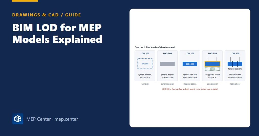
A client asks for an “LOD 400 MEP model” and three people on the team picture three different things: one thinks of nicer graphics, one of manufacturer families, one of fabrication spools. LOD is not about how pretty the model looks — it is about how much you can rely on each element, and it is set per element, not per model.
The levels, in MEP terms
The most used definitions come from the LOD Specification published by BIMForum, which builds on the earlier AIA definitions. Each step says what the model user may rely on:
| LOD | Ductwork | Pipework | Equipment (AHU, pump, board) |
|---|---|---|---|
| 100 | Zones or airflow per area, no routes | Schematic lines, no sizes | Symbol or area allowance in a plant room |
| 200 | Main routes with approximate sizes | Mains with approximate sizes and levels | Generic box of approximate size and weight |
| 300 | Sized ducts at design level, fittings, terminals | Sized pipes at design level, main valves | Specified size, connections and clearances |
| 350 | + insulation, hangers, access zones, sleeves | + supports, slope, insulation, sleeves | + connection points to other trades, maintenance space |
| 400 | Fabrication sections, joints, seams, gauges | Spools, joints, every fitting and support | Approved product with exact geometry |
Level of development vs level of detail
“Level of detail” is how much graphic detail an element has; “level of development” is how much a user can trust its geometry and data. A highly detailed manufacturer object placed at a guessed location is still only LOD 200 in practice, because nobody should set out from it. A plain box with the correct size, weight, position and connection points can be LOD 300 or 350. Reviewers judge the information, not the rendering.
LOD and ISO 19650
ISO 19650 projects do not use the LOD numbers directly. They describe the level of information need for each purpose — geometry, alphanumeric information and documentation — in the information requirements. Many teams still use LOD numbers as a shorthand for the geometry part, so read the project’s information standard and use its wording in your BIM execution plan.
What this means on an MEP project
- Set LOD per element and stage. A model element table lists each category (duct, pipe, cable tray, equipment, supports) with the target LOD at each stage and who is responsible. “The model is LOD 300” means nothing on its own.
- Clash detection needs LOD 350 for the critical items. Without insulation, hangers and access zones, the clash test misses exactly the problems site will find — see the MEP coordination clash checklist.
- Quantities follow LOD. At 200 you can estimate; from 300 you can measure; supports and small fittings often only exist at 350–400. Our MEP quantity take-off tips show what to add by rule.
- Shop drawings sit at LOD 400. Fabrication sections and exact products are the contractor’s work, checked with the MEP shop drawing review checklist.
- Do not over-model early. Modelling hangers at concept stage wastes time that is better spent on the void budget and routing.
- Keep sheets and layers consistent. Drawings cut from the model still need the MEP drawing layer and sheet standards.
LOD definitions and targets vary by edition and project — verify with the current LOD Specification, the project BIM execution plan and any national or client BIM standard.
Ready-made drawings and tools for your next project
CAD block libraries, detail drawings and AutoCAD tools made by practising MEP engineers.
FAQ
What does LOD 300 mean for an MEP model?
The elements are specific systems with sizes, shapes, locations and orientations that can be measured directly from the model, such as sized ducts and pipes at their design levels. Supports, insulation detail and access zones are typically added at LOD 350.
Is LOD 500 more detailed than LOD 400?
No. LOD 500 means the element has been verified on site and the model is an as-built record. It says nothing about extra graphic or fabrication detail.
Which LOD do I need for clash detection?
For reliable MEP coordination the main services should be at least LOD 350, so that insulation, supports, connections and maintenance clearances are in the model. LOD 300 finds the large clashes only.
PAFTA – Sheet Splitter & Merger for AutoCAD
See a whole tender set as one drawing: merge a folder of DWG, DXF and vector PDF files, convert vector PDF to DWG and split any drawing back into sheets.
Free install from the Microsoft Store · 30-day trial · licence 20 € for all your devices or €15 per computer on our site